8
Part Names and Functions
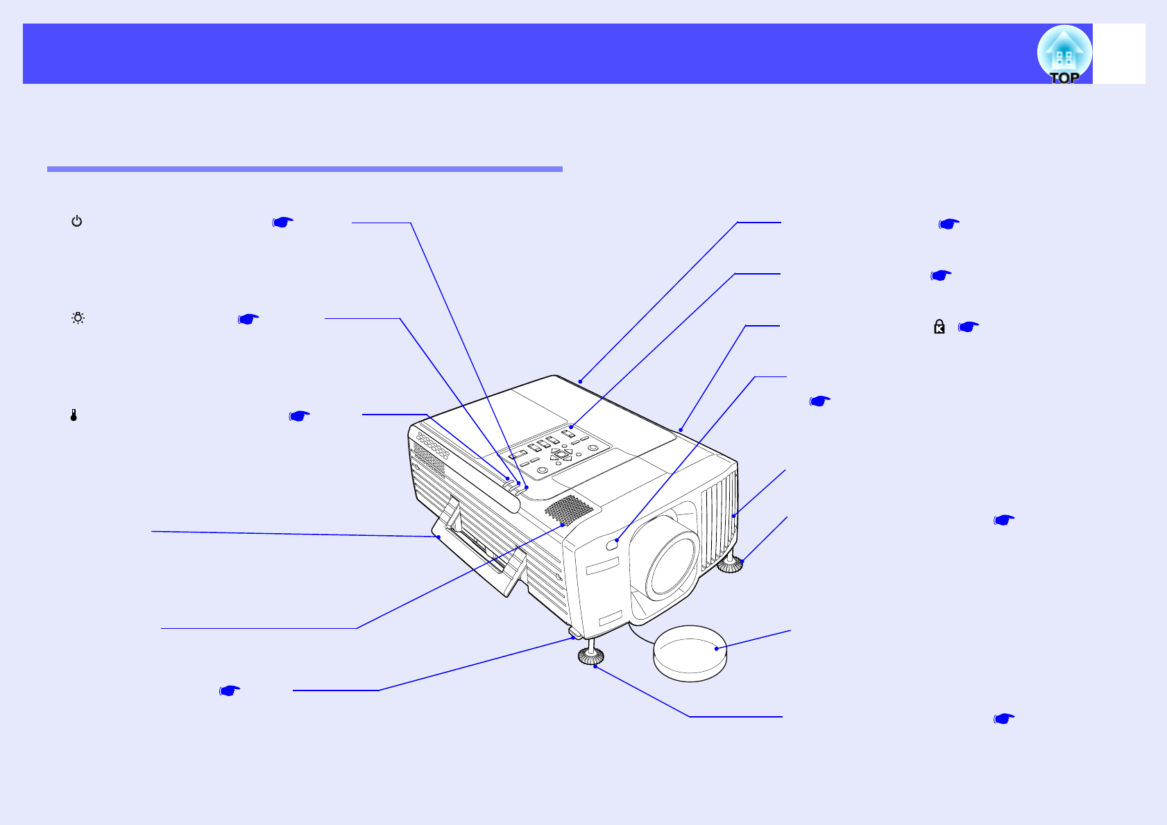
The illustration below shows the projector with a standard lens fitted.
Front/Top/Side
•
••
•
Remote control light-receiving area
p.14
Receives signals from the remote control.
•
••
•
Speaker
•
••
•
Handle
Use this handle when lifting and transporting
the projector.
•
••
•
(Operation) indicator p.116
Flashes or lights in different colours to
indicate the operating status of the projector.
•
••
•
(Lamp) indicator p.116
Flashes or lights in different colours to
indicate problems with the projection lamp.
•
••
•
(Temperature) indicator p.116
Flashes or lights in different colours to
indicate problems with the internal
temperature of the projector.
•
••
•
Foot adjust lever p.51
Another foot adjust lever is located on the
right side.
Pull both foot adjust levers when extending
and retracting the front adjustable feet.
•
••
•
Control panel p.10
•
••
•
Security lock ( ) p.144
•
••
•
Air exhaust vent
•
••
•
Lens cover
Attach when not using the projector in order to
prevent the lens from becoming dirty or damaged.
•
••
•
Front adjustable foot p.51
Extend and retract to adjust the projection angle
when the projector is placed on a surface such as
a shelf.
•
••
•
Front adjustable foot p.51
Extend and retract to adjust the projection
angle when the projector is placed on a surface
such as a shelf.
•
••
•
Air intake vent p.131


