


DXP DVI, DXP DVI Pro, and DXP HDMI Series • Installation 7
Installation
This section describes the rear panels of the DXP switchers and provides instructions for
cabling. It covers the following topics:
• Rear Panels
• Connections
Rear Panels
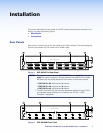
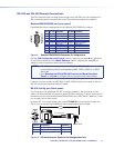
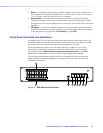
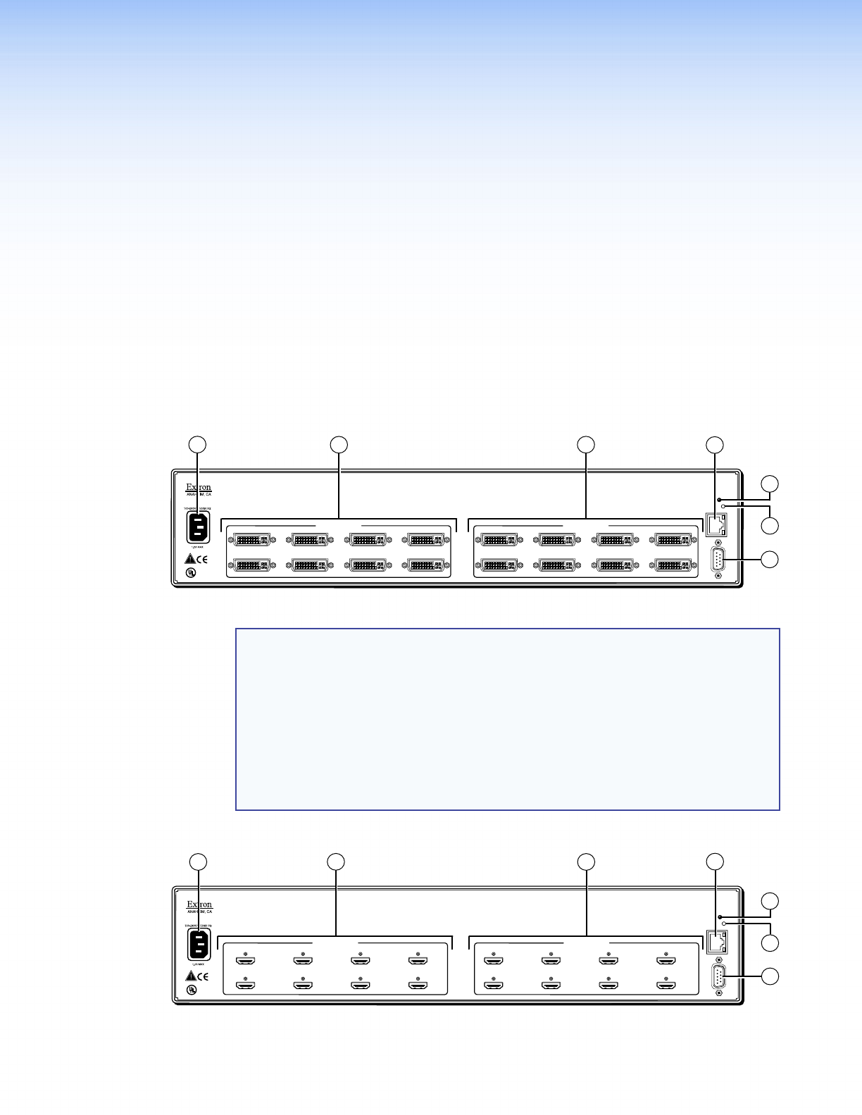
Most of the connectors are on the rear panels of the DXP switchers. The following figures
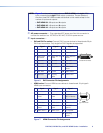
show the rear panels of a DVI model and an HDMI model.
DVI-D INPUTS
LISTED
1T23
I.T.E.
C
U S
78
13
5
24
6
DVI-D OUTPUTS
DVI PRO - HDCP COMPLIANT
78
13
5
24
6
RESET
LAN
LINKACT
RS232/RS422
REMOTE
1
3
4
7
5
6
2
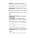
Figure 4. DXP 88 DVI Pro Rear Panel
NOTES: • The illustration above shows a DXP 88 DVI Pro, with eight DVI input and
eight DVI output connectors. The rear panels of the other DVI Pro models
are identical to this model except for the number of inputs and outputs:
• DXP DVI Pro 84 – 8 inputs and 4 outputs
• DXP DVI Pro 48 – 4 inputs and 8 outputs
• DXP DVI Pro 44 – 4 inputs and 4 outputs
• The DXP 44 and 48 DVI (non-Pro) rear panels are identical to their DVI Pro
counterparts except that they do not contain the “DVI Pro – HDCP
Compliant” designation.
Fig_DXP HDMI rear panel
HDMI INPUTS
LISTED
1T23
I.T.E.
C
U S
78
13
5
24
6
HDMI OUTPUTS
HDMI - HDCP COMPLIANT
78
13
5
24
6
RESET
LAN
LINKACT
RS232/RS422
REMOTE
2
1
3
4
7
5
6
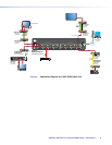
Figure 5. DXP 88 HDMI Rear Panel