


DXP DVI, DXP DVI Pro, and DXP HDMI Series • Operation 32
I/O Grouping
I/O grouping allows you to subdivide the front panel control of the matrix into four smaller
functional sub-switchers. Inputs and outputs can be assigned to one of four groups or not
assigned to any group.
When you are creating ties on the front panel, inputs and outputs that are assigned to a
group can be tied only to other outputs and inputs within the same group. For example,
you cannot tie an input that is assigned to group 1 to an output that is assigned to
group 2. Ungrouped inputs and outputs can be switched to outputs and inputs in any
group. Ties between groups (for example, an input in group 1 tied to an output in group 2)
can be created via SIS commands, the control software, or the web pages.
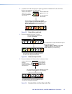
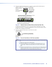
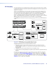
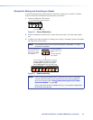
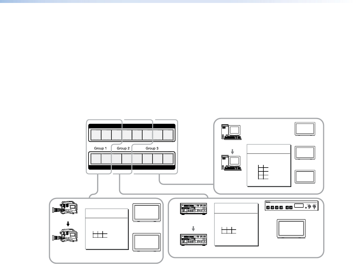
Figure 46 gives an example of input and output grouping of DVI Pro and HDMI devices on
a DXP.
1 2 3 4 5 6 7 8
OUTPUTS
3 input, 2 output
matrix
Camera #1
Monitor
Monitor
Group 1
123
Input
1
2
Output
Camera #3
1
DVS 304 IP
DIGITAL VIDEO SCALER
ADJUST
IR
2 3 4 MENU NEXT
VTR
(MPEG-2/JPEG 2000) #1
VTR
(MPEG-2/JPEG 2000) #3
3 input, 2 output
matrix
Monitor
Group 2
3
4
456
Input
Output
DVS 304
Editing Station
#1
Monitor
Monitor
Monitor
2 input, 4 output
matrix
5
6
7
8
78
Input
Output
Group 3
Editing Station
#2
1 2 3 4 5 6 7 8
INPUTS
Figure 46. I/O Grouping of Incompatible Video Formats
Suggested applications for the I/O grouping feature include:
• Segregating specific video formats to prevent an input in one video format from
being inadvertently applied to an output device that supports another video format
(see figure 46).
• Segregating input and output devices that are in separate rooms.
• Isolating video from being displayed on specific output devices for operational security
reasons.
I/O groups can be set up using the front panel, SIS commands via RS-232 or RS-422
control (see the “SIS Configuration and Control” section, beginning on page 49), the
embedded web pages (see the “HTML Operation” section, beginning on page 105), or
the Matrix Switchers Control Program via RS-232, RS-422, or IP control (see the “Matrix
Software” section, beginning on page 72).