


DXP DVI, DXP DVI Pro, and DXP HDMI Series • SIS Configuration and Control 61
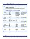
Command
ASCII Command
(Host to Switcher)
Response
(Switcher to Host)
Additional Description
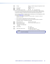
View Ties and Presets (continued)
View audio room preset
configuration
E
X^
*
X*
*01*2VC
} X@•X@•
...
•X@•
Aud
]
Show room
X^
, preset
X*
audio configuration. Show
input
X@
tied to 16 sequential
outputs assigned to room
X^
,
starting from Output 1.
NOTE: For all DXP models, the recommended starting output number is 1.
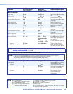
View video global preset
configuration
E
X&
*1*1VC
} X@
•
X@
•...•
X@
•Vid
]
Show preset
X&
video
configuration. Show the input
(
X@
) tied to 16 sequential
outputs, starting from
output 1.
NOTES: • For all DXP models, the starting output number is 1.
• The response shows 16 outputs regardless of the number of outputs your DXP actually has. All outputs in
excess of the number of outputs on your switcher are shown as dashes (–).
• To view the current video configuration, enter
EX&
*1*1VC
}
where
X&
= 0.
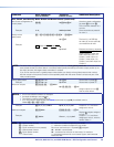
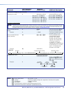
Example:
DXP 88 DVI Pro/
DXP 88 HDMI
E
4*1*1VC
}
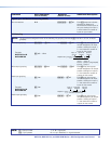
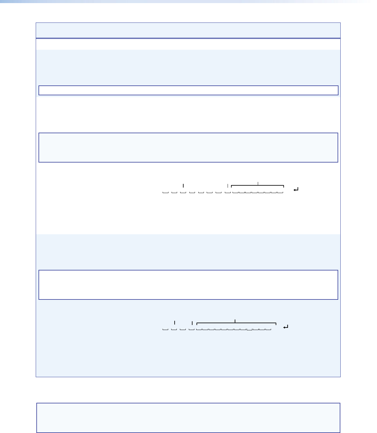
1Output:
Response = tied input:
Input 2 tied to output 3
234567891011 12
8 • 8 • 2 • 8 • 8 • 7 • 7 • 0 • – • – • – • – • – • –
• – • – • Vid
13 1415 16
No tied
input
No outputs
Each position shown in the response is an output: left = starting output (1), right = starting
output +15 (16). The number in each position is the input tied to that output.
In this example, preset 4, video Input 8 is tied to Outputs 1, 2, 4, and 5; Input 2 is tied to
Output 3; and Input 7 is tied to Outputs 6 and 7. No input is tied to Output 8. Outputs 9
through 16 do not exist on the DXP, so they are shown as having no tied inputs.
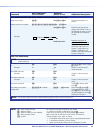
View audio global preset
configuration
E
X&
*01*2VC
} X@
•
X@
•...•
X@
•Aud
]
Show preset
X&
audio
configuration. Show the input
(
X@
) tied to 16 sequential
outputs, starting from
Output 1.
NOTES: • For all DXP models, the starting output number is 1.
• The response shows 16 outputs regardless of the number of outputs your DXP actually has. All outputs in
excess of the number of outputs on your switcher are shown as dashes (–).
• To view the current audio configuration, enter
E
X&
*1*2VC
}
where
X&
= 0.
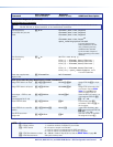
Example:
DXP 84 DVI Pro
DXP 84 HDMI
E
15*1*2VC
}
See below.
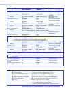
Output:
Response = tied input:
Input 6 tied
to output 2
2 • 6 • 1 • 0 • – • – • – • – • – • – • – • – • – • – • – • – • Aud
No tied
input
No outputs
123456789101112131415 16
Each position shown in the response is an output: left = starting output (1),
right = starting output +15 (16). The number in each position is the input tied to that output.
Outputs 5 through 16 are not present on the DXP 84 models.
In this example, preset 15, audio Input 1 is tied to Output 3, Input 2 is tied to Output 1,
and Input 6 is tied to Output 3. No input is tied to Output 4. Outputs 5 through 16 are not
present on this switcher.
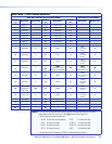
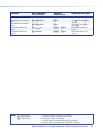
NOTE:
X@
= Input number (for ties) 0 – maximum number of inputs for your model
X^
= Room number (for room presets) Each room can have up to 10 presets (
X*
) assigned.
X&
= Global preset number 00 – 32. 00 = current preset
X*
= Room preset number 00 – current ties for the room in view mode, 10 maximum