


DXP DVI, DXP DVI Pro, and DXP HDMI Series • Installation 8
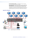
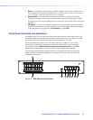
NOTE: Figure 5 on the previous page shows a DXP 88 HDMI, with eight HDMI
input connectors and eight HDMI output connectors. The rear panels of
the other three DXP HDMI models are identical to this model except for the
number of inputs and outputs:
• DXP HDMI 84 – 8 inputs and 4 outputs
• DXP HDMI 48 – 4 inputs and 8 outputs
• DXP HDMI 44 – 4 inputs and 4 outputs
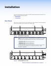
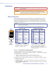
a AC power connector — Plug a standard IEC power cord into this connector to
connect the switcher to a 100 VAC to 240 VAC, 50-60 Hz power source.
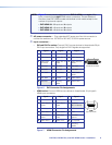
b Input connectors —
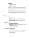
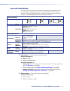
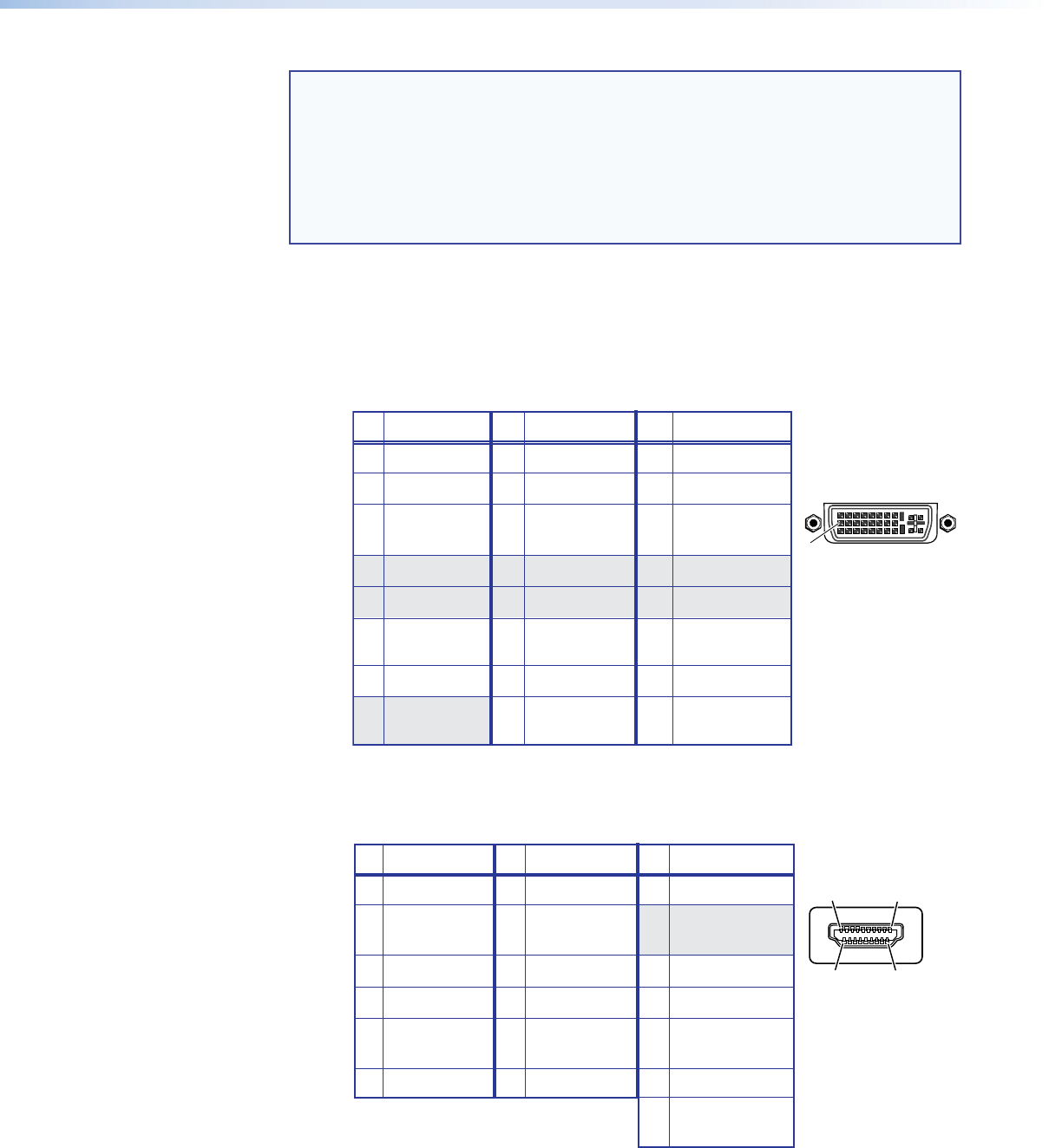
• DVI and DVI Pro series: Connect DVI-D source devices to these female 29-pin
DVI-I input connectors. Only single-link DVI-D signals are supported.
8 Not used 16 Hot plug 24 TMDS clock–
detect
Pin
Signal
Pin Signal
Pin
Signal
1 TMDS data 2– 9 TMDS data 1– 17 TMDS data 0–
2 TMDS data 2+ 10 TMDS data 1+ 18 TMDS data 0+
3 TMDS data 11 TMDS data 1/3 19 TMDS data 0/5
2/4 shield shield shield
4 Not used 12 Not used 20 Not used
5 Not used 13 Not used 21 Not used
6 DDC clock 14 +5 V power 22 TMDS clock
shield
7 DDC data 15 Ground 23 TMDS clock+
1
8
17
24
9
Female DVI Connector
Figure 6. DVI Connector Pin Assignments
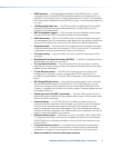
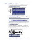
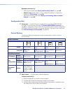
• HDMI series: Connect HDMI source devices to these female 19-pin type A
HDMI input connectors.
Pin
Signal
Pin Signal
Pin
Signal
1 TMDS data 2+ 7 TMDS data 0+ 13 CEC
2 TMDS data 2 8 TMDS data 0 14 Reserved
shield shield (NC on device)
3 TMDS data 2– 9 TMDS data 0– 15 SCL
4 TMDS data 1+ 10 TMDS clock+ 16 SDA
5 TMDS data 1 11 TMDS clock 17 DDC/CEC
shield shield ground
6 TMDS data 1– 12 TMDS clock– 18 +5 V power
19
Hot plug
detect
HDMI
Type A Connector
1
182
19
Figure 7. HDMI Connector Pin Assignments