


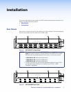
DXP DVI, DXP DVI Pro, and DXP HDMI Series • Installation 11
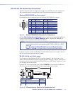
RS-232 and RS-422 Remote Connections
The DXP switchers have two serial ports through which the DXPs can be configured via
SIS commands (serial commands that control the switcher through this connector).
Remote RS232/RS422 port (rear panel)
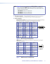
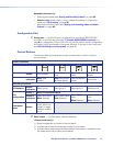
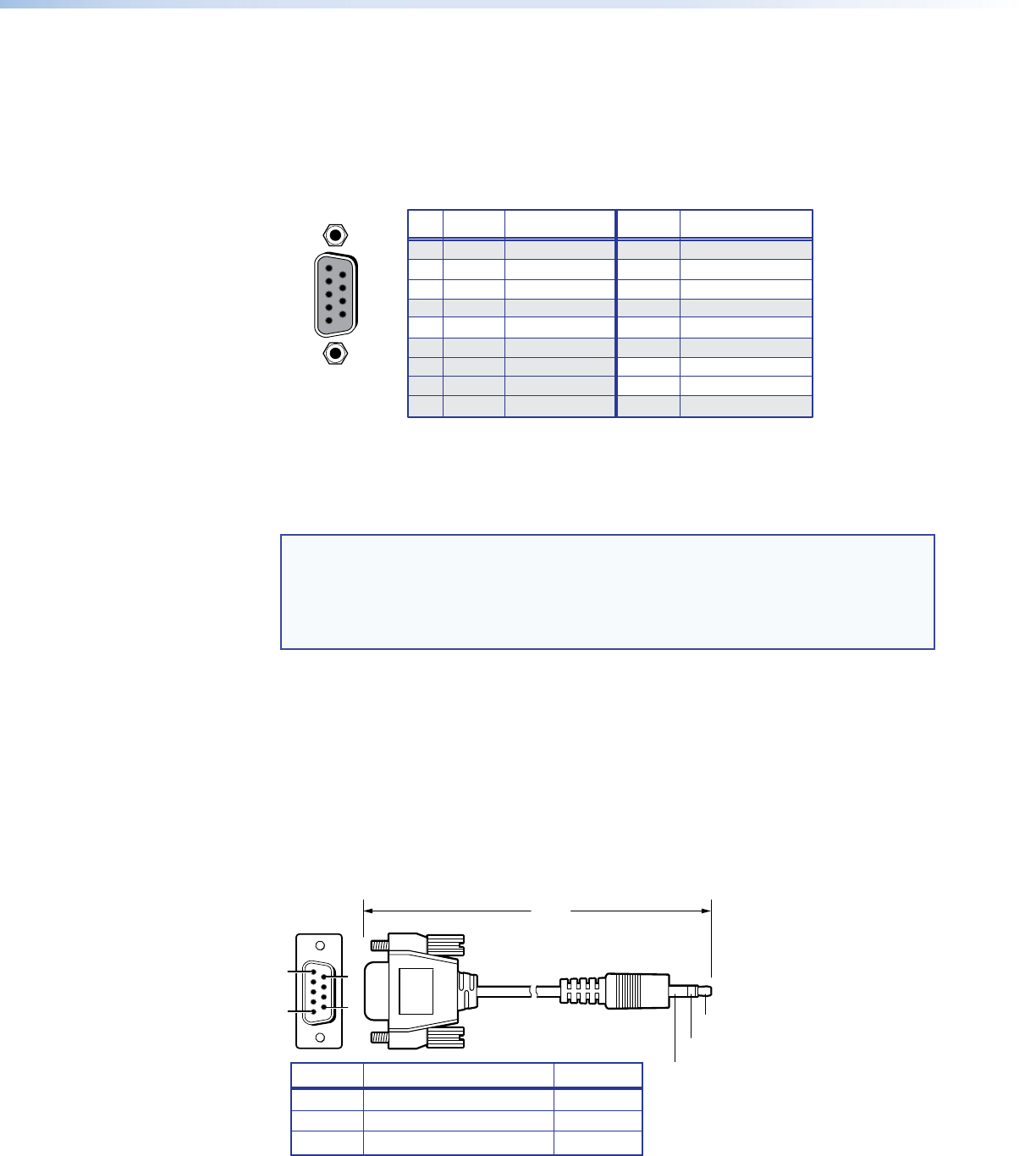
Figure 9 shows the pin assignments for the Remote RS232/RS422 connector.
RS-232 FunctionPin Function
1
2
3
4
5
6
7
8
9
—
Tx
Rx
—
Gnd
—
—
—
—
Not used
Transmit data
Receive data
Not used
Signal ground
Not used
Not used
Not used
Not used
—
Tx–
Rx–
—
Gnd
—
Rx+
Tx+
—
Not used
Transmit data (–)
Receive data (–)
Not used
Signal ground
Not used
Receive data (+)
Transmit data (+)
Not used
RS-422
5
1
9
6
RS232/RS422
REMOTE
Figure 9. Remote RS232/RS422 Connector Pin Assignments
See the “SIS Configuration and Control” section, beginning on page 49, for definitions
of the SIS commands and the “Matrix Software” section, beginning on page 72, for
details on how to install and use the control software.
NOTES: • The switcher can support either the RS-232 or RS-422 serial
communication protocol, and operate at 9600, 19200, 38400, or 115200
baud rate.
• See “Selecting the RS-232/RS-422 Protocol and Baud Rate (Rear
Panel)” on page 44 to configure this port using the front panel buttons.
If desired, you can connect an MKP 2000 or MKP 3000 remote control panel to this port.
See the user guide of either product for details.
RS-232 Config port (front panel)
The Config port is an additional RS-232 connector, located on the front panel. A host
device can be connected to this port for serial RS-232 control only. Protocol for the port is
the same as for the rear panel Remote RS232/RS422 port: 9600 baud, 8 data bits, 1 stop
bit, no parity, and no flow control.
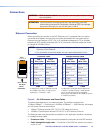
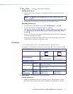
An optional 2.5 mm cable (Extron part number 70-335-01) can be used to connect the
DXP to your computer. Figure 10 shows the pin assignments for this cable.
6 feet
(1.8 m)
Part #70-335-01
5
1
9
6
Sleeve (Gnd)
Ring
Tip
6
9
9-pin D Connection TRS Plug
Pin 2 Computer Rx line Tip
Pin 3 Computer Tx line Ring
Pin 5 Computer signal ground Sleeve
Figure 10. 2.5 mm Connector Cable for the Configuration Port