


GSS 100 Graphic Still Store • Installation
Installation
GSS 100 Graphic Still Store • Installation
2-2
2-3
Mounting the GSS
Tabletop/desktop placement
For tabletop or desktop placement only, install the self-adhesive
rubber feet (provided) onto the four corners of the bottom of the
enclosure.
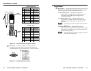
Rack mounting
UL requirements
The following Underwriters Laboratories (UL) requirements
pertain to the installation of the GSS into or onto a rack (figure
2-1).
1. Elevated operating ambient — If installed in a closed
or multi-unit rack assembly, the operating ambient
temperature of the rack environment may be greater
than room ambient. Therefore, consider installing the
equipment in an environment compatible with the
maximum ambient temperature (Tma) specified by the
manufacturer.
2. Reduced air flow — Installation of the equipment in a rack
should be such that the amount of air flow required for
safe operation of the equipment is not compromised.
3. Mechanical loading — Mounting of the equipment in
the rack should be such that a hazardous condition is not
achieved due to uneven mechanical loading.
4. Circuit overloading — Consideration should be given to
the connection of the equipment to the supply circuit and
the effect that overloading of the circuits might have on
overcurrent protection and supply wiring. Appropriate
consideration of equipment nameplate ratings should be
used when addressing this concern.
5. Reliable earthing (grounding) — Reliable earthing
of rack-mounted equipment should be maintained.
Particular attention should be given to supply connections
other than direct connections to the branch circuit (such as
the use of power strips).
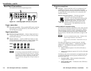
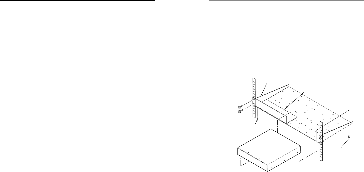
Installation instructions
1. If feet were installed on the bottom of the GSS 100, remove
them.
2. Place the GSS 100 on one half of the 1U (one unit high, one
unit wide) rack shelf (part #60-190-01). Align the front of
the GSS with the front of the shelf, and align the threaded
holes on the bottom of the GSS with the holes in the rack
shelf.
3. Attach the GSS to the rack shelf with the two provided
4-40 x 3/16" machine screws. Insert the screws from
the underside of the shelf, and securely fasten them into
diagonally-opposite corners (figure 2-1).
Use 2 mounting holes on
opposite corners.
(2) 4-40 x 3/16"
Screws
NOTE: Using screws longer
than 3/16” will damage the
unit and void the warranty.
RSU 129 1U Universal Rack Shelf
Front false
faceplate
uses 2
screws.
1/2 Rack Width Front False
Faceplate
Figure 2-1 — Rack mounting the GSS 100
4. Attach the false front panel (provided with the rack shelf)
to the unoccupied side of the rack (as shown above), or
install a second half-rack-width device on that side by
repeating steps 1 – 3.
5. Attach the rack shelf to the rack using four 10-32 x ¾” bolts
(provided with the shelf). Insert the bolts through the
provided #10 beveled washers, then through the holes in
the rack ears and rack (figure 2-1).