


GSS 100 Graphic Still Store • Installation
Installation, cont’d
GSS 100 Graphic Still Store • Installation
2-6
2-7
Clip DownSide
1
1&2
3&6 4&5
7&8
2345678
1Pins 2345678
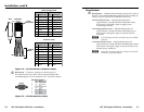
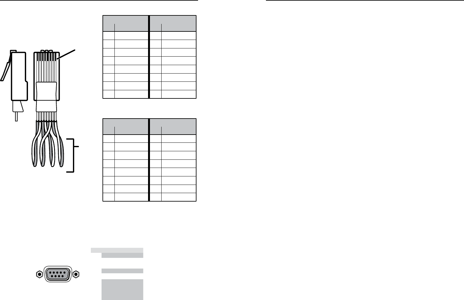
RJ-45
connector
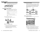
Patch (straight) cable
Twisted
Pairs
Side 1 Side 2
Pin Wire color Pin Wire color
1 White-orange 1 White-orange
2 Orange 2 Orange
3 White-green 3 White-green
4 Blue 4 Blue
5 White-blue 5 White-blue
6 Green 6 Green
7 White-brown 7 White-brown
8 Brown 8 Brown
Crossover cable
Side 1 Side 2
Pin Wire color Pin Wire color
1 White-orange 1 White-green
2 Orange 2 Green
3 White-green 3 White-orange
4 Blue 4 Blue
5 White-blue 5 White-blue
6 Green 6 Orange
7 White-brown 7 White-brown
8 Brown 8 Brown
Figure 2-4 — RJ-45 connector and pinout tables
e
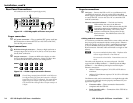
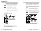
RS-232 port — Connect a computer or control system to
this 9-pin D connector to allow remote control using the SIS
commands (figure 2-5). See chapter 4, SIS™ Control, for details.
RS-232
PIN
RS-232 Function
1
— None
None
None
None
None
None
2
TX Transmit data
3
RX Receive data
4
—
5
Gnd Ground
6
—
7
—
8
—
9
—
Figure 2-5 — RS-232 connector pinout
Reset button
f
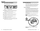
Reset button — The Reset button initiates three levels of reset to
the GSS. Press and hold the button while the GSS is running or
while you power up the GSS for different reset levels.
• Events (mode 3) reset — Hold the Reset button for
approximately 3 seconds (the Reset LED blinks once),
then release it and push it again to toggle events
monitoring on and off.
• IP settings (mode 4) reset — Hold the Reset button for
approximately 6 seconds (the Reset LED blinks twice),
then release it and push it again to reset the GSS’s IP
functions.
N
The IP settings reset does not replace any user-installed
firmware.
• Absolute (mode 5) reset — Hold the Reset button for
approximately 9 seconds (the Reset LED blinks three times),
then release it and push it again to restore the GSS to the
default factory conditions.
N
Image files, IP settings, and user settings are all cleared
and reset to the factory default.