


GSS 100 Graphic Still Store • Operation
Operation
GSS 100 Graphic Still Store • Operation
3-2
3-3
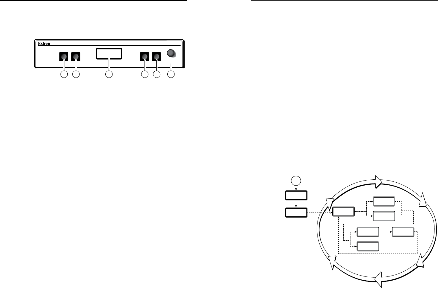
Front Panel Controls and Indicators
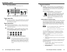
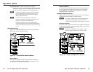
Figure 3-1 shows the controls and indicators on the front panel
of the GSS 100. See Front Panel Operations for details on using
these controls and indicators.
GSS 100
ADJUST/
SELECT
IMAGE
TAKE
MENU
NEXT
1 3 5 2 4 6
Figure 3-1 — GSS 100 front panel
a
Image button — Press this button to activate the menu on the
LCD display (
c
) that allows you to select between the pass-
through input and one of the stored images.
b
Take button — Press this button to select either the pass-
through input or one of the stored images.
c
LCD display — The 8-column by 2-line LCD screen displays
output and configuration menus and status information.
d
Menu button — Press the Menu button to enter and move
through the main menu system in the GSS.
e
Next button — Press the Next button to step through the
submenus in the GSS menu system.
f
Adjust/Select knob — Rotate the Adjust/Select knob to change
settings when it is used in conjunction with the Image and Take
buttons or the Menu and Next buttons.
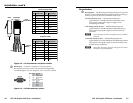
Front Panel Operations
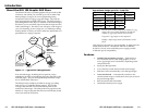
Plug in all system components and turn on the input device
(such as a desktop or laptop computers) and the output monitor.
Use the LAN port to upload one or more still images to the GSS.
Select either the pass-through input or one of the stored still
images to output (see Selecting an image to display). The image
should appear on the monitor connected to the output.
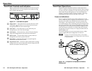
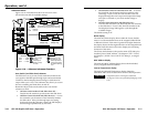
Power-on indications
Power is applied when the power cord is connected to an AC
source. When AC power is applied, the GSS performs a self-test
that shows the model name and the firmware version in the
LCD display. After approximately 3 seconds, the LCD reverts
to its default display cycle, alternating among four displays that
show the model name, the currently displayed image (the pass-
through input or one of the previously loaded images by its file
name), the output resolution (of a stored image only; the pass-
through input is output exactly as it is input), and the unit’s IP
address (figure 3-2).
The current settings are saved in nonvolatile memory. When
power is applied, the latest configuration is retrieved.
N
On figure 3-2 and all other flowcharts in this chapter,
dashed lines indicate screen changes that are the result of
a timeout function.
Default Cycle
3 sec.
3 sec.
Power
on
3 sec.
3 sec.
or
3 sec.
Extron
GSS 100
Extron
GSS 100
1024 x
768 @72
I192.168
P255.255
RGB
PASSTHRU
or
Viewing
Image
Viewing
PassThru
Version
n.nn
3 sec.
Figure 3-2 — LCD power-on displays and default
display cycle