


GSS 100 Graphic Still Store • Installation
Installation, cont’d
GSS 100 Graphic Still Store • Installation
2-4
2-5
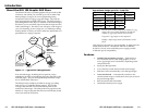
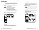
Rear Panel Connections
All connectors are on the rear panel (figure 2-2).
R
R
50/60 Hz
RS-232
LAN
RESET
G
G
B
B
H/HV
H/HV
V
V
100-240V .3A MAX
RGB PASS-THRU
OUTPUT
2
3 6
1
4 5
Figure 2-2 — GSS 100 graphic still store rear panel
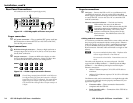
Power connection
a
AC power connector — Plug a standard IEC power cord into
this connector to connect the GSS to a 100 VAC to 240 VAC,
50 or 60 Hz power source.
Signal connections
b
RGB Pass-through connectors — Connect a high resolution or
computer input (VGA, SVGA, XGA, SXGA, or UXGA) to these
female, BNC connectors.
c
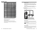
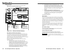
Output connectors — Connect an RGB video display or other
device to these female BNC connectors. Figure 2-3 shows how
to connect the RGB video format for each configuration.
RGBHV
R
RGBS
G B H/HV V
R G B H/HV V
Figure 2-3 — Video output connection format
N
The still image output format (RGBHV or RGBS) must
be configured using the front panel controls or a Simple
Instruction Set™ (SIS™) command. The output format
applies only to the output of still images stored in the
GSS; the RGB Pass-through video is output exactly as it
is input.
Remote connections
d
LAN port — Connect the GSS to a PC or to an Ethernet LAN,
via this RJ-45 connector. You can use the GSS’s embedded
HTML pages to upload still images from the PC to the GSS and
to control the GSS. You can also use a PC to control the GSS
with SIS commands.
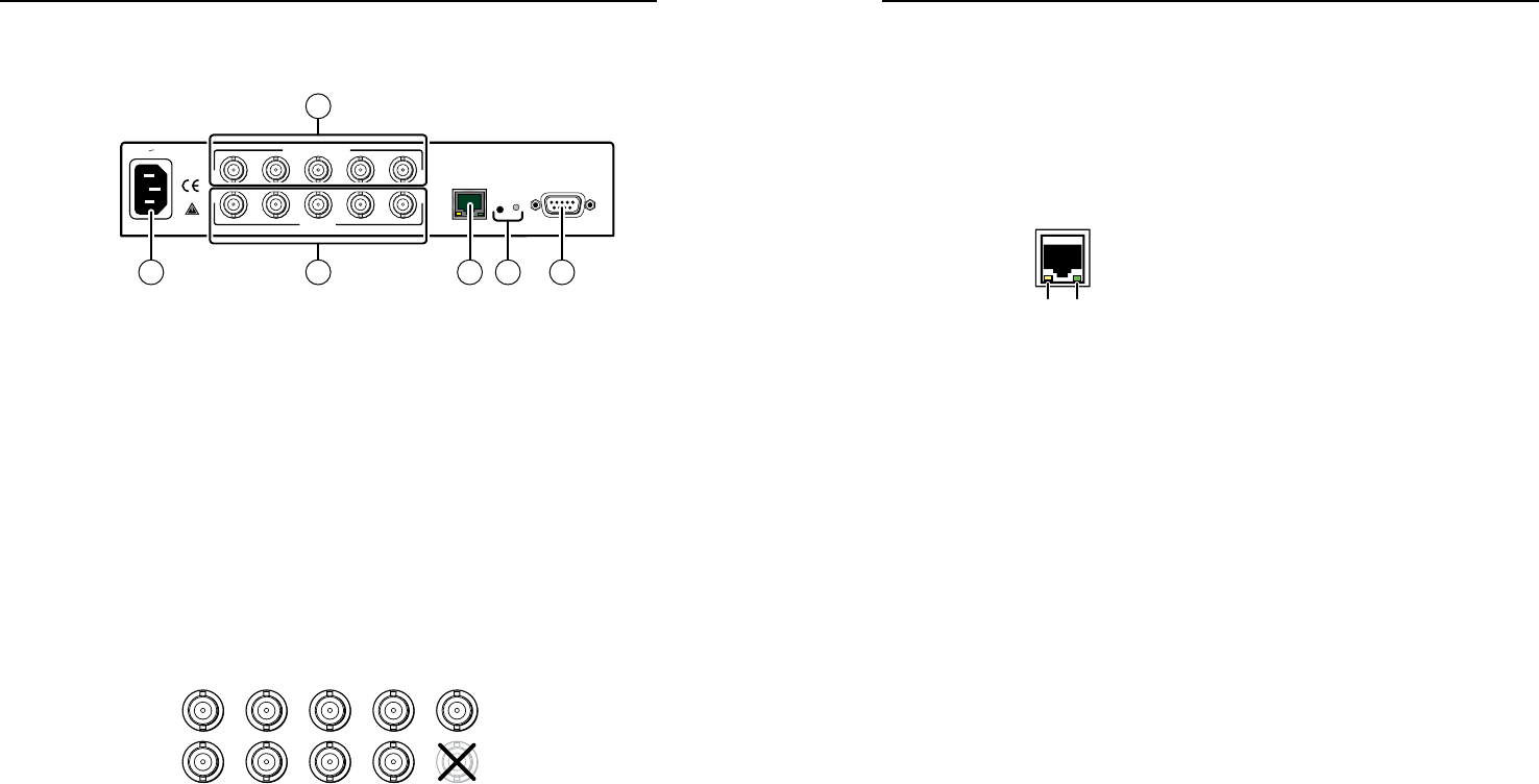
Ethernet connection indicators — The Link and Activity
LEDs indicate the status of the Ethernet
connection. The Link LED indicates that the GSS
is properly connected to an Ethernet LAN. This
LED should light steadily. The Activity LED
indicates transmission of data packets on the
RJ-45 connector. This LED flickers as the GSS
communicates.
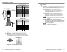
Cabling and RJ-45 connector wiring
It is vital that your Ethernet cables be the correct cables, and that
they be properly terminated with the correct pinout. Ethernet
links use Category (CAT) 5e or CAT 6, unshielded twisted pair
(UTP) or shielded twisted pair (STP) cables, terminated with
RJ-45 connectors. Ethernet cables are limited to a length of 328’
(100 m).
N
Do not use standard telephone cables. Telephone cables
will not support Ethernet or Fast Ethernet.
Do not stretch or bend cables. Transmission errors can
occur.
The cable used depends on your network speed. The GSS
supports both 10 MBps (10Base-T — Ethernet) and 100 MBps
(100Base-T — Fast Ethernet), half-duplex and full-duplex
Ethernet connections.
• 10Base-T Ethernet requires CAT 3 UTP or STP cable at
minimum.
• 100Base-T Fast Ethernet requires CAT 5e UTP or STP cable
at minimum.
The Ethernet cable can be terminated as a straight-through cable
or a crossover cable and must be properly terminated for your
application (figure 2-4).
• Crossover cable — Direct connection between the
computer and the GSS 100.
•
Patch (straight) cable — Connection of the GSS 100 to
an Ethernet LAN.
Link
LED
Activity
LED