


Installation, cont’d
System 7SC • Installation2-8
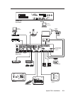
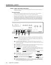
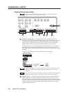
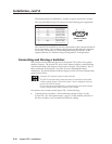
Control device connections
Captive screw and 3.5 mm stereo jack connectors are included with the
switcher, but the installer provides the cables.
RS-232
PROJ CONTROL
CONTACT CLOSURE
RELAY 1 RELAY 2
12
DISPLAY PWR
SENSOR
IR COMM
RGB
H/HV
V
SCP/AAP CONTROL
OUTPUTS
RGB
12345 ABCDEABCDE67
EDCBA ABCDEFGHIJ
EDCBAEDCBA
R
R-Y
G/Y
VID
H/HV
V
B/C
B-Y
R
R-Y
G/Y
VID
H/HV
V
B/C
B-Y
5 6
1 4
5 6
7
2
3
1
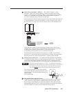
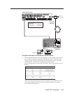
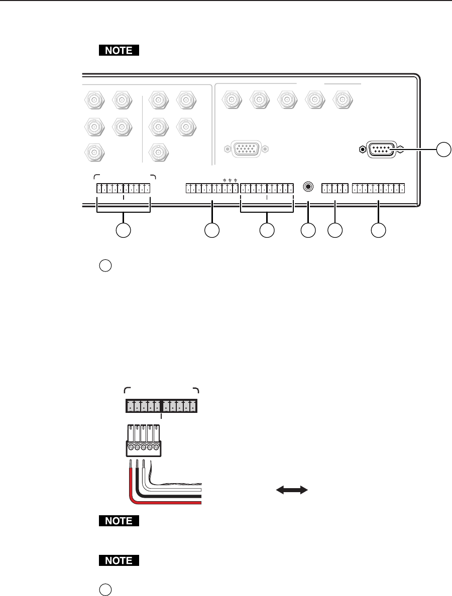
SCP/AAP Control ports — Connect Extron SCP control pads (SCP 250,
SCP 200, or SCP/AAP A) to these 5-pole captive screw connectors to provide
remote control of the System 7SC. The SCPs replicate several of the front
panel controls. The SCP 200 and SCP 250 are also able to receive infrared
signals from the IR 701 remote control and send them to the switcher.
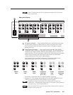
In total, up to sixteen (16) control pads in any combination can connected to
these ports if they are linked together with cables such as Extron’s Comm
Link cable. Refer to the appropriate SCP user’s manual for details and wiring
diagrams.
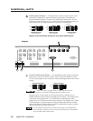
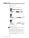
The SCP/AAP Control port has the following pin assignments:
12
SCP/AAP CONTROL
EDCBA
To / from
SCP 200,
SCP 250,
or SCP/AAP A
EDCBA
E
D
C
B
A
Ground (shield/drain)
Ground (black)
Comm. signal (white)
+12 VDC (red)
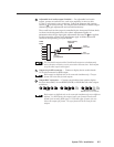
Each port provides up to 12 VDC for powering the SCP control pads or other
devices. However, the total load for both ports combined must not exceed
1 ampere.
The load (such as an SCP control pad or interface) should not be placed further
than a maximum of 300 feet (91.4 meters) from the System 7SC switcher.
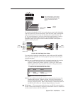
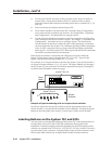
2
Contact closure — Connect an optional contact closure control device here.
Select an input channel by making contact closure between an input’s pin
(pins 1 through 7 correspond to inputs 1 through 7) and a ground pin (pins 8,
9, and 10). Continuous connections made by contact closure override all other
means of selection: continuous contact closure takes precedence over front
panel and RS-232 selection.