


2-9System 7SC • Installation
3
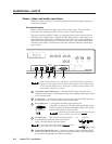
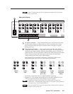
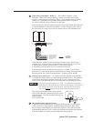
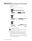
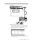
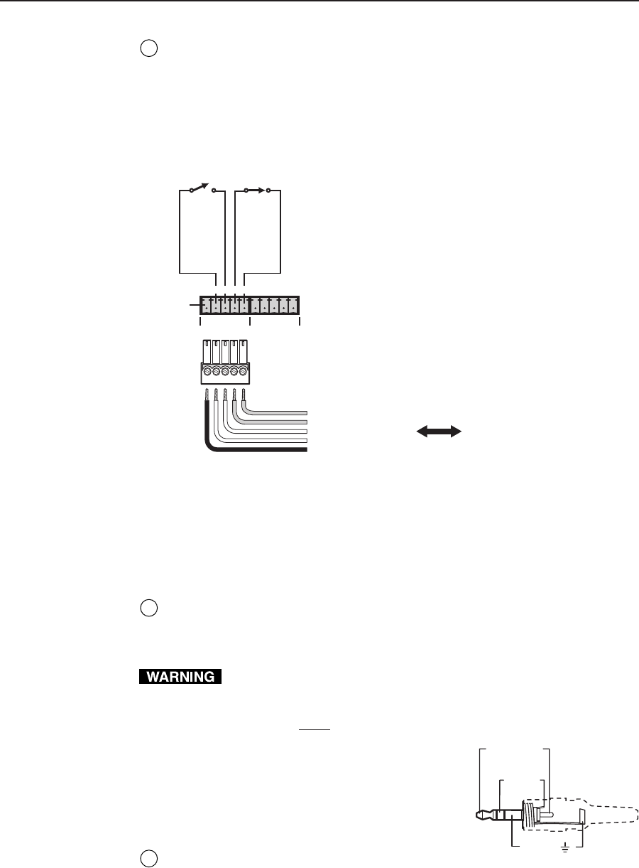
Room/relay ports (Relay 1, Relay 2) — These allow control of “room”
functions – items such as room lighting, window coverings, and display
screens – via momentary or latching contact. These contacts may be used to
control any equipment as long as the contact specifications of a total of
24 volts at 1 ampere are not exceeded for each port.
Each relay has two sets of contacts: one pair is closed by default, the other pair
is open by default, as shown below. Both of a relay’s contacts can be used at
the same time, so a total of four sets of contacts can be used simultaneously.
Normally closed (2)
Normally closed (1)
Normally open (2)
Normally open (1)
Not
used
System 7SC
Relay ports
A
ABC
RELAY 2RELAY 1
DEBCDE
To / from
room control
equipment
Normally closed (2)
Normally closed (1)
Normally open (2)
Normally open (1)
Not used
A
B
C
D
E
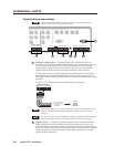
When the room function is active, the closed contacts open, and the open
contacts close. Contacts can be programmed to operate in one of two ways:
• latching (brief contact) (press to turn on, press to turn off), or
• momentary (timed) (press to turn on, timeout to turn off).
In the timed mode the default timeout period is
1
/8 second. Use the front
panel menus or the control software for Windows to change the length of the
timeout period. See “Serial Communication”, chapter four, for details.
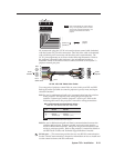
4
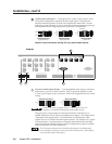
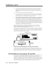
Display power sensor port — This mini stereo-style jack allows connection
of an optional display power (current) sensor (part #60-271-01). The sensor is
used to keep the projector and the System 7SC in sync. Refer to the Power
Sensor User’s Guide, part #68-391-01, for information on operating the sensor.
The power sensor port supplies +12 VDC. To avoid electric shock when
connecting the cable from the power sensor into the System 7’s rear panel
port, always connect the stereo jack at one end of the cable to the power
sensor unit before plugging the jack at the other end into the System 7.
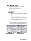
The wiring connections are the same on both
ends of the cable that connects the power sensor
to the System 7. Wire the included connector as
shown at right.
Use a 3-wire cable.
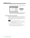
5
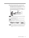
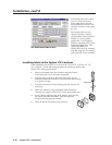
IR communications port (IR Comm) —
Connect the included IR Emitter or optional IR Broadcaster via this captive
screw connector to send learned/uploaded IR signals (which differ from
IR 701 remote control signals) to control the projector. The signals from the
optional IR Broadcaster cover a wider area and greater distance than do those
from the emitter, so it can be placed further from the projector.
Sleeve ( )
Ring
(signal)
Tip (+12 V)