


Installation, cont’d
System 7SC • Installation2-12
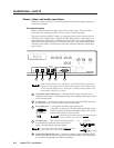
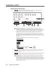
Connecting and Slaving a Switcher
One switcher can be connected (slaved) to the System 7SC to allow for a greater
number of inputs. The System 7SC serves as the master switcher, communicating
with and providing video output to the projector/display. The switcher (“slave”)
that is connected to the System 7 provides up to ten (10) additional input
connections. See the illustration on the next page for a list of Extron switchers that
can be used as slaves.
A System 7SC cannot be used as a slaved switcher.
The RS-232 and video cable connections must be made between the slaved
switcher and the System 7 before the System 7 can be configured (via front
panel or RS-232) for slaving.
Do not attach any communications or control devices to the slaved switcher
except a contact closure remote control, if one is needed.
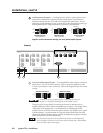
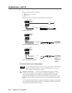
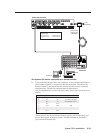
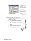
To connect a slave switcher to the System 7SC, do the following:
1. Connect the slave switcher’s video and audio outputs to input 1 of the
System 7SC. See “Rear panel inputs”, page 2-5, in this manual, and refer to
the slave switcher’s user’s manual for details on cabling.
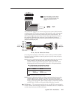
The default protocol is 9600 baud, 1 stop bit, no parity, and no flow control.
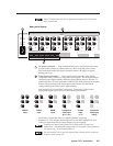
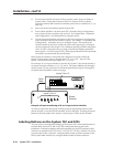
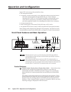
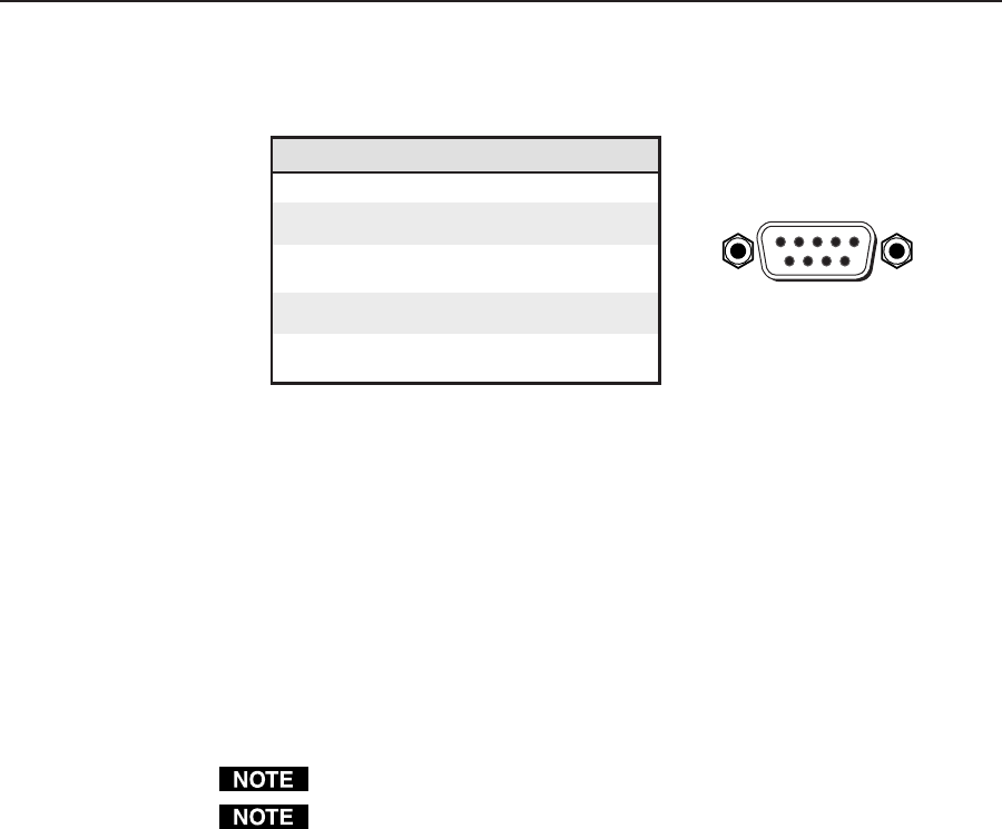
The rear panel RS-232 9-pin D connector has the following pin assignments:
Pin RS-232 function Description
1 – No connection
2 Tx Transmit data
3 Rx Receive data
4 Tx 2 Transmit data
5 Gnd Signal ground
6 – No connection
7 – No connection
8 Rx 2 Receive data
9 – No connection
DB9 Pin Locations
Female
51
96
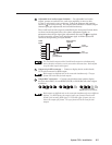
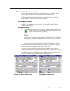
Pins 4 and 8 (Tx2 and Rx2) are used to communicate with a slaved switcher (if
one is connected). A slave adapter cable (Extron part #26-386-01) is required
for slaving. For details, see “Connecting and Slaving A Switcher” in this
chapter, and also see “Switcher Setup/Configuration” in chapter three.