


2-13System 7SC • Installation
RS-232
PROJ CONTROL
CONTACT CLOSURE
RELAY 1
IR TRANSPORT
RELAY 2
12
DISPLAY PWR
SENSOR
IR COMM
RGB
H/HV
V
INPUTS
AUDIO IN
SCP/AAP CONTROL
OUTPUTS
RGB
Anaheim, CA
100
-
240
50/60 Hz
1.3A MAX.
1
LR
1
LR
2
LR
3
LR
4
LR
5
LR
6
LR
12345
ABCDEABCDE
67
EDCBAABCDEFGHIJ
FIXED VARIABLE
ABCDEEDCBAEDCBA
R
R-Y
G/Y
VID
H/HV
V
B/C
B-Y
R
R-Y
G/Y
VID
H/HV
V
B/C
B-Y
R
R-Y
G/Y
VID
H/HV
V
B/C
B-Y
R
R-Y
G/Y
VID
H/HV
V
B/C
B-Y
R
R-Y
G/Y
VID
H/HV
V
B/C
B-Y
R
R-Y
G/Y
VID
H/HV
V
B/C
B-Y
2 3 4 5 6
LR
AUDIO OUT
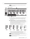
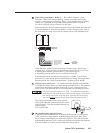
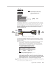
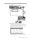
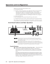
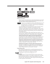
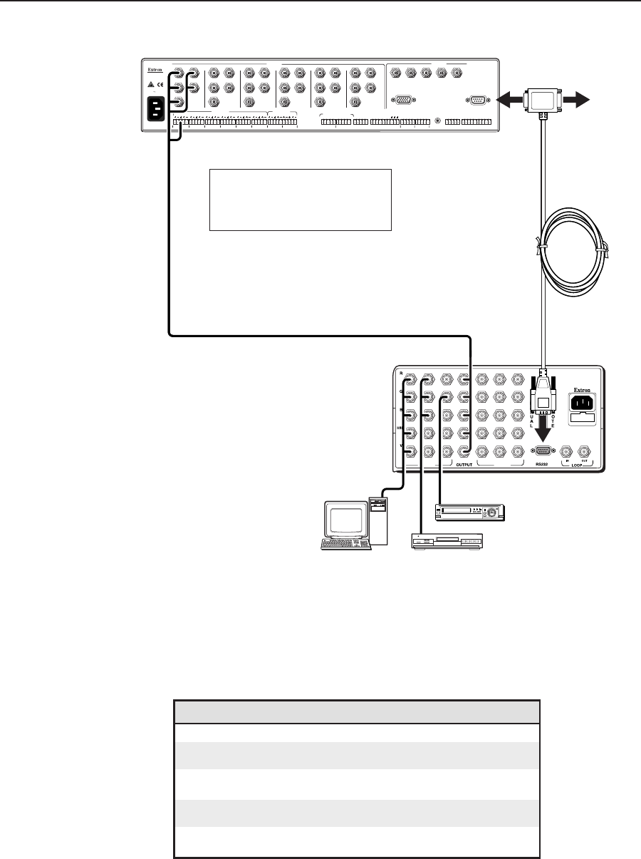
System 7SC Rear Panel
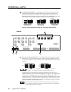
Slave Switcher
Rear Panel
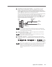
Host
Computer
Slave Cable
Extron part
# 26-386-01
90-240 VAC, 50/60 Hz
FUSE: 250V, 400mA SLO-BLO
INPUTS INPUTS
531246
Computer
DVD
VCR
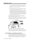
These Extron switchers can be slaved to
the System 7SC:
• System 8 PLUS • SW4 AR MX HV
• System 10 PLUS • SW 6 AR MX HV
The System 7SC master connected to a slaved switcher
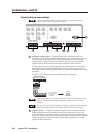
2. Connect the RS-232 ports of the two switchers. A slave adapter cable (Extron
part number 26-386-01), is required for RS-232 connection. This allows the
master (System 7), the slaved switcher, and the host device to be connected
simultaneously. The RS-232 communication is bidirectional.
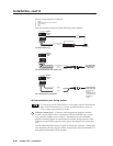
The pin assignments for each of the slave cable’s three 9-pin connectors are as
follows:
Pin System 7 Host Slave switcher
1– – –
2 Tx Rx Tx 2 (slave to host)
3 Rx Tx Rx 2 (host to slave)
4 Tx 2 *Tx 2 –
5 Gnd Gnd Gnd
6– – –
7– – –
8 Rx 2 *Rx 2 –
9– – –
*Pins 4 and 8 on the host connector must be used for Tx2 and Rx2 only, and
not for other signals in the host system. If needed, disable or disconnect
pins 4 and 8 on the host side.