


Serial Communication, cont’d
System 7SC • Serial Communication4-10
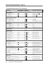
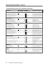
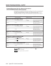
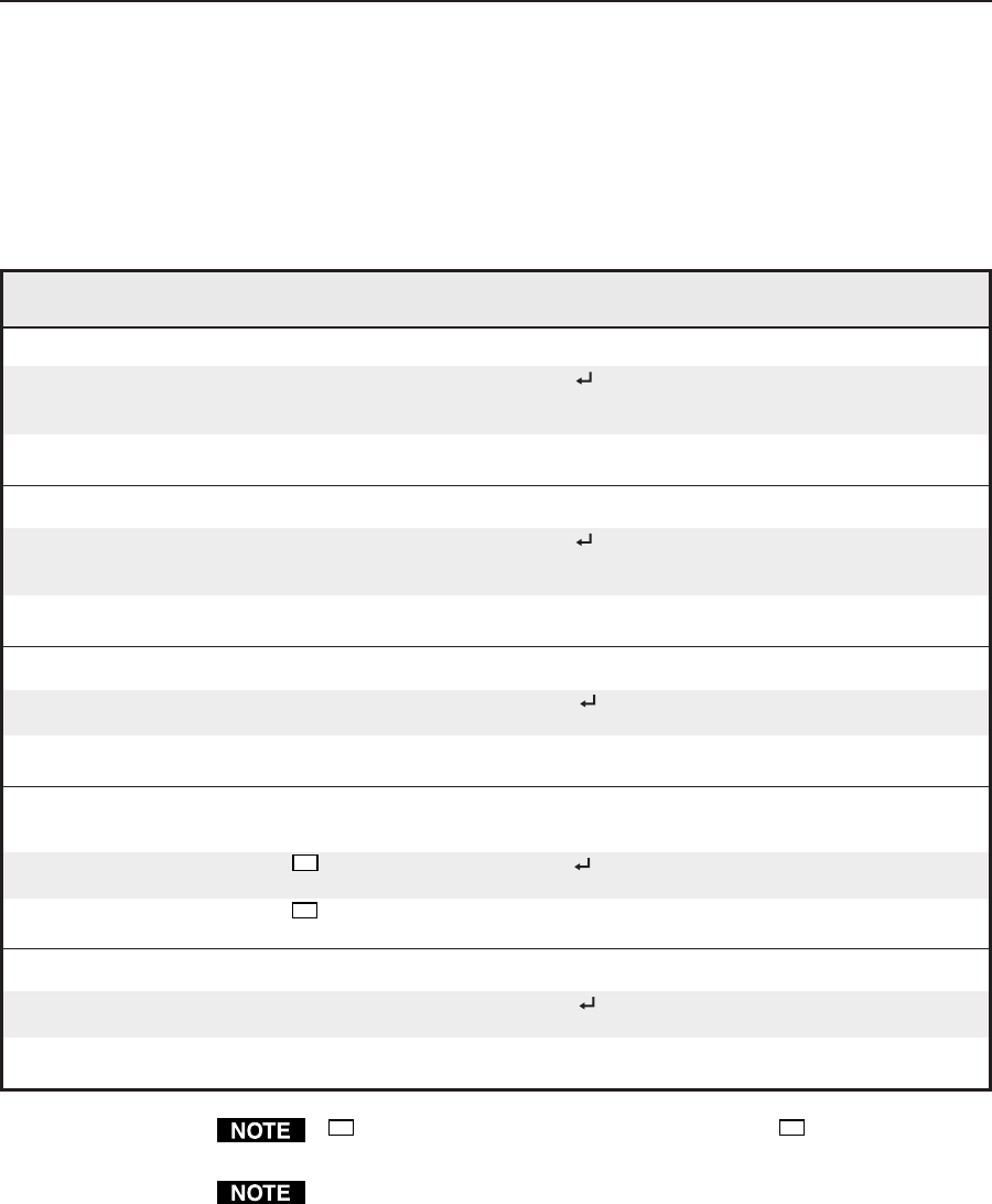
Command Hex. command Response Additional description
(host to switcher) (switcher to host)
Send/receive data to/from page 0 memory
Send 80 A0 [16k bytes of data] Dnl0 The host downloads 16k bytes
of binary data to page 0 of the
System 7’s memory.
Recieve 80 A1 The System 7 sends 16k bytes of
binary data to the host.
Send/receive data to/from page 1 memory
Send 80 A2 [16k bytes of data] Dnl1 The host downloads 16k bytes
of binary data to page 1 of the
System 7’s memory.
Receive 80 A3 The System 7 sends 16k bytes of
binary data to the host.
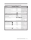
Send/receive a flag (parameter) block
Send 80 A4 [32 bytes of data] Prm0 The host sends 32 bytes of binary
parameter data to the System 7.
Receive 80 A5 The System 7 sends 32 bytes of
binary parameter data to the host.
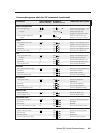
Send/receive a segment (256 bytes) of data
(a segment relating to a single button)
Send 80 A6
??
[256 bytes of data] Seg0 The host sends 256 bytes of
binary data to the System 7.
Receive 80 A7
??
The System 7 sends 256 bytes of
binary data to the host.
Send/receive 512 bytes of channel (button) data
Send 80 A8 [512 bytes of data] EEP0 The host sends 512 bytes of
binary data to the System 7.
Receive 80 A9 The System 7 sends 512 bytes of
binary data to the host.
??
indicates the block number in hex notation where
??
can be 0 to 7F (hex)
(0 to 127 decimal).
The responses shown are ASCII.
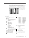
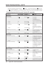
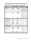
Command/response table for advanced instructions
(for the Windows-based control program)
Data downloads/uploads are initiated by sending a series of hex commands to the
host RS-232 port of the System 7 switcher. The Windows-based control program
uses these commands mainly to load and save driver data and system
configuration settings. See page 3-6 for information on projector control memory.