


System 7SC • Serial Communication4-2
Serial Communication
The System 7SC can be remotely controlled via a host computer or other device
(such as a control system) attached to the rear panel RS-232 connector. The control
device (host) can use either Extron’s Simple Instruction Set (SIS) commands or the
graphical control program for Windows.
The switcher uses a protocol of 9600 baud, 1 stop bit, no parity, and no flow control.
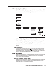
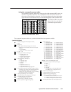
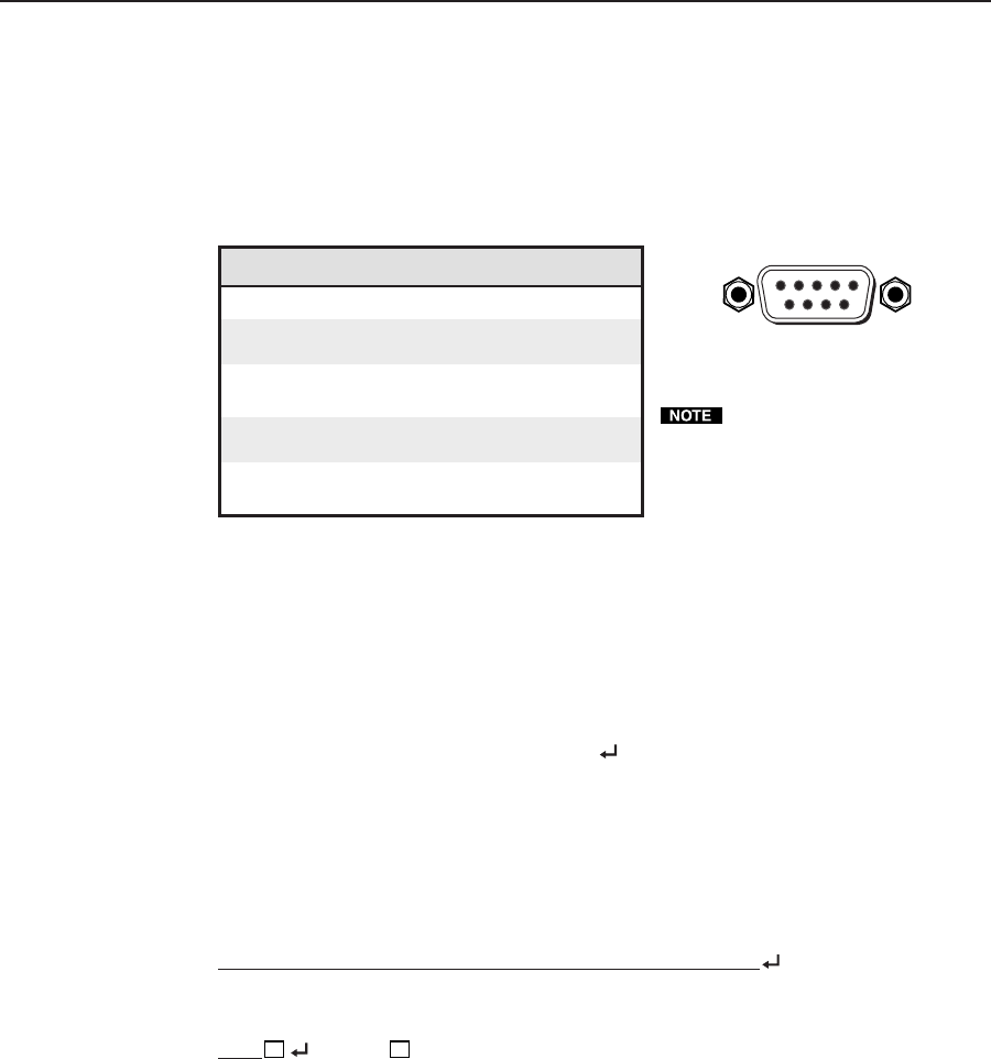
The rear panel RS-232 9-pin D connector has the following pin assignments:
Pin RS-232 function Description
1 – No connection
2 Tx Transmit data
3 Rx Receive data
4 Tx 2 Transmit data
5 Gnd Signal ground
6 – No connection
7 – No connection
8 Rx 2 Receive data
9 – No connection
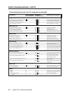
RS-232 Programmer’s Guide
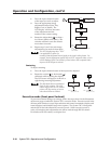
Host-to-switcher communications
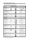
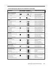
SIS commands consist of one or more characters per field. No special characters
are required to begin or end a command sequence. When the System 7SC
determines that a command is valid, it executes the command and sends a
response to the host device. All responses from the switcher to the host end with a
carriage return and a line feed (CR/LF = ), which signals the end of the response
character string. A string is one or more characters.
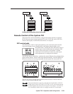
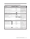
Switcher-initiated messages
When a local event such as a front panel (or SCP control pad) selection or
adjustment takes place, the System 7SC switcher responds by sending a message to
the host. No response is required from the host. The switcher-initiated messages
are listed here (underlined).
(C) Copyright 2001, Extron Electronics, System 7SC, Vx.xx
The System 7SC sends the copyright message when it first powers on. Vx.xx is the
firmware version number.
C hn
X1
(where
X1
is the input number)
The System 7SC sends this response when an input is switched. C = both audio
and video were switched.
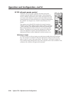
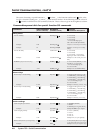
Error responses
When the switcher receives a valid SIS command, it executes the command and
sends a response to the host device. If the System 7SC is unable to execute the
command because the command is invalid or it contains invalid parameters, it
returns an error response to the host.
The error response codes and their descriptions are as follows:
E01 – Invalid input channel number (the number is too large)
E10 – Invalid command
E13 – Invalid value (the number is out of range/too large)
E16 – Unit is busy
E23 – Checksum error.
Pins 4 and 8 on the host connector
must be used for Tx2 and Rx2 only
(for communicating with a slaved
switcher), and not for other signals in
the host system. If needed, disable or
disconnect pins 4 and 8 on the host side.
DB9 Pin Locations
Female
51
96