


Installation, cont’d
System 7SC • Installation2-10
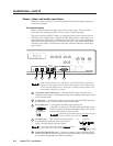
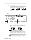
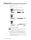
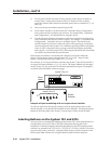
The pin assignments are as follows:
Signal
Display power/current sensor detection
Carrier & signal
Gnd
+12 V
E
D
C
B
A
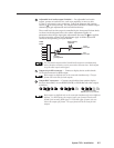
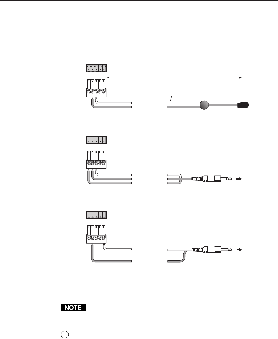
Wire the connector using one of the following wiring options.
D
C
E
D
C
D
A
IR Emitter
White Striped Wire Only
100'
(30.5 m)
(Demodulated IR)
Carrier & Signal
Gnd*
System 7
IR Comm
Port
For the IR Emitter only
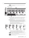
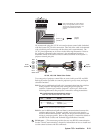
IR COMM
ABCDE
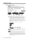
Carrier & signal
Gnd
Gnd
+12 V
System 7
IR Comm
Port
For the IR Broadcaster with emitter port
IR COMM
ABCDE
Signal
System 7
IR Comm
Port
For a wired projector remote port
IR COMM
ABCDE
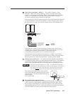
To the projector's
wired remote port
(Connector type
and pin
configurations may
vary depending on
the projector
model.)
To IR Broadcaster
with emitter port
(#60-272-02)
IR Communications port wiring options
For some projectors the emitter must be used together with the IR Broadcaster.
Refer to the IR Broadcaster User’s Guide (part #68-392-02) or contact an
Extron support representative for details.
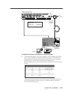
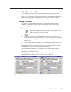
6
Projector control port — Connect a cable between the projector and this
3.5 mm, 10-pole captive screw connector for RS-232 or RS-422 one- or two-
way projector/display device control. Commands from a downloaded
projector control program or user-defined command strings entered via the
Windows-based control program can be sent to the display device from this
port.
Use the following illustration as a guide to wiring the connector. Wiring will
vary depending on the projector model. In most cases only the transmit (Tx)
and ground connections will be needed.