


4-3System 7SC • Serial Communication
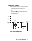
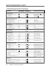
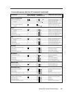
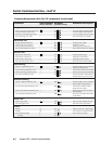
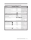
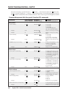
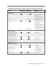
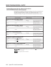
Using the command/response tables
The command/response tables on the next page list valid command ASCII codes, the
switcher’s responses to the host, and a description of the command’s function or
the results of executing the command. Except when setting audio gain/attenuation,
upper and lower case characters may be used interchangeably in the command field.
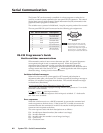
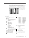
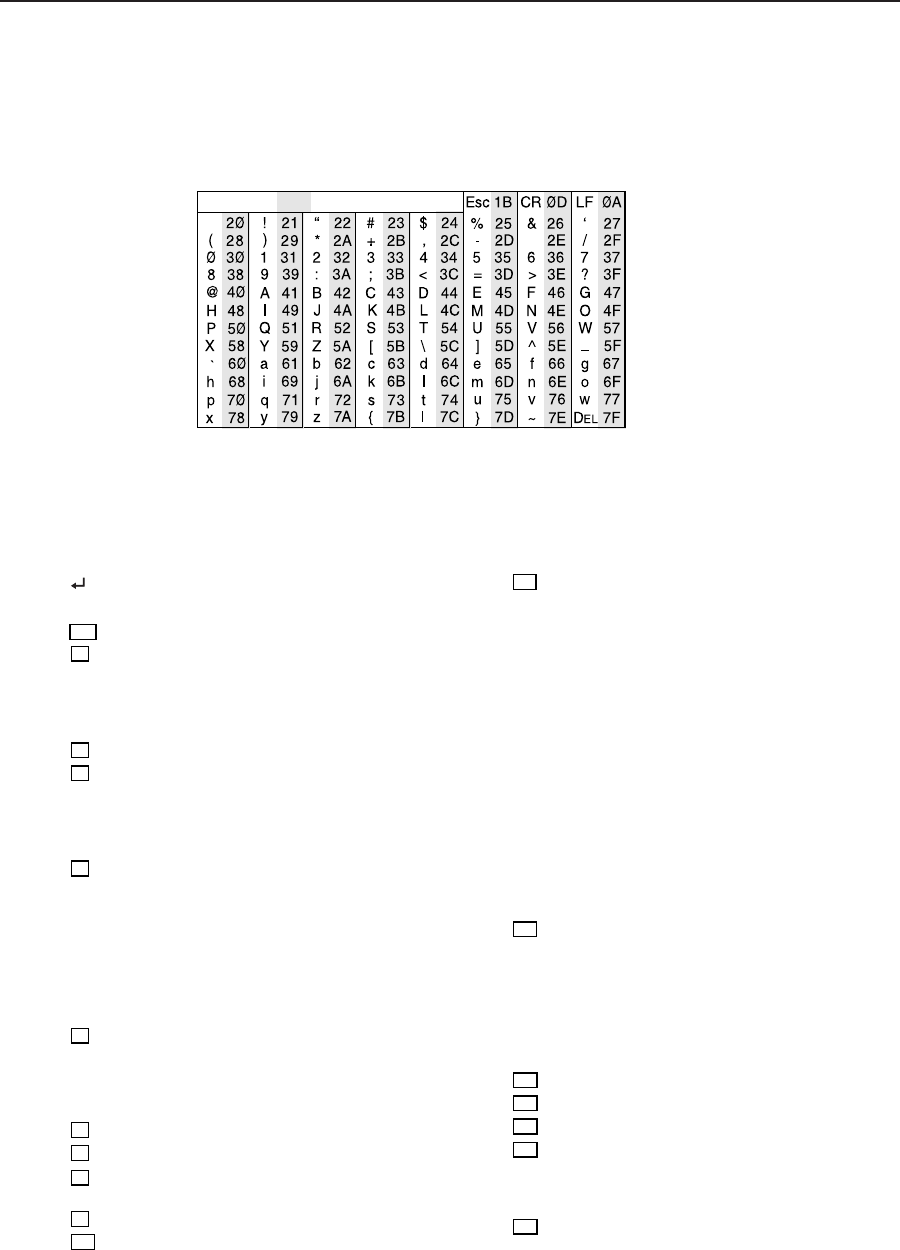
The ASCII to HEX conversion
table at left is for use with the
command/response tables.
ASCII to HEX Conversion Table
•
ASCII to Hex conversion table
X11
= Scaler output rate
1 = 640x480 @ 50 Hz
2 = 640x480 @ 60 Hz
3 = 640x480 @ 75 Hz
4 = 640x480 @ Lock*
5 = 800x600 @ 50 Hz
6 = 800x600 @ 60 Hz
7 = 800x600 @ 75 Hz
8 = 800x600 @ Lock
9 = 832x624 @ 60 Hz
10 = 832x624 @ 75 Hz
11 = 832x624 @ Lock
12 = 848x480 @ 60 Hz
13 = 852x480 @ 60 Hz
14 = 1024x768 @ 50 Hz
15 = 1024x768 @ 60 Hz
16 = 1024x768 @ 75 Hz
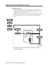
The command/response tables use symbols (defined below) to represent variables.
17 = 1024x768 @ Lock
18 = 1280x768 @ 56 Hz
19 = 1280x1024 @ 50 Hz
20 = 1280x1024 @ 60 Hz
21 = 1280x1024 @ Lock
22 = 1360x765 @ 60 Hz
23 = 1365x1024
@ 60 Hz
24 = 1365x1024
@
Lock
25 = 480p (HDTV), 60 Hz
26 = 480p @ Lock
27 = 720p (HDTV), 60 Hz
28 = 720p @ Lock
29 = 1080p (HDTV), 60 Hz
30 = 1080p @ Lock
31 = 1080i (HDTV), 60 Hz
32 = 1080i @ Lock
Symbol definitions
= CR/LF (carriage return/line feed) (hex 0D 0A)
• = Space
Esc
= Escape key
X1
= Specific input number (0 through 7 if no slave is
attached, 0 to 16 maximum with a slaved 10-input
switcher)
0 = no connection
1 = input 1, 2 = input 2, and so forth
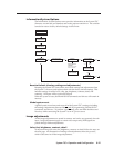
X2
= 0 = off, 1 = on
X3
= Display power status (0 through 3)
0 = display power is off
1 = display power is on
2 = display is powering down
3 = display is powering up
X4
= Video signal type (0 through 7)
0 = RGB
1 = composite video
2 = composite video
3 = S-video
4 = S-video
5 = component video (YUV)
6 = component video (YUV)
7 = component video (YUV), progressive
X5
= One through the maximum possible number of inputs
(1 through 7 up to 16) for the connected equipment
(7 for a stand-alone System 7, 16 if a 10-input
switcher is slaved to the System 7) See “Connecting
and Slaving a Switcher” in chapter two.
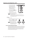
X6
= Audio gain (0 through 18) in ½ dB steps
X7
= Audio attenuation (1 through 30) in ½ dB steps
X8
= Controller firmware version (listed to
two decimal places e.g.: x.xx)
X9
= Numeric value (-15 through +9) in dB
X10
= Picture adjustment range (0 through 255)
*NOTE: Lock is Accu-RATE Frame Lock
™
X12
= Detected input signal standard (0 through 4)
0 = none
1 = NTSC 3.58
2 = PAL
3 = NTSC 4.43
4 = SECAM
– = not applicable (occurs when the input is
set for RGB, YUV, or progressive YUV)
X13
= Detail level (0 through 63)
X14
= Volume adjustment range (0 through 100%)
X15
= Adjustment range (1 through 15)
X16
= Executive mode status (0 through 2)
0 = disabled (executive mode off, normal mode on)
1 = enabled, image adjustments are locked
2 = enabled, all front panel features are locked
X17
= Blanking adjustment range (0 through 127 lines)