


Operating manual
CNC 8070
6.
EDITING-SIMULATION MODE
Editing window
(SOFT V03.0X)
100
6.2.2 Import DXF files
DXF files may be imported from the editor to the program being edited. See
"6.3.2 File" on page 103.
The DXF format is standard for exchanging graphic files. Importing this type of files
makes it possible to generate the part-program directly from a drawing. The DXF file
may consist of points, lines and arcs. It can also consist of polylines, but they must
be previously uncombined.
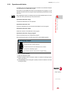
When selecting this option, the CNC shows a list of the programs that may be
imported into the one being edited. Select the desired program from the list and press
[ENTER].
After selecting the file, define how the various layers of the DXF file are to be converted
into ISO code. Once this data has been set, press the "Convert" softkey to import the
file into the part-program.
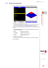
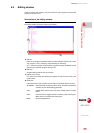
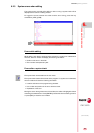
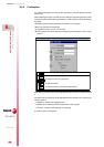
DXF file configuration
When importing a DXF file, it shows the configuration window to define how the
different layers of the drawing must be treated. The configuration window shows three
areas clearly and distinctly.
Layer description area
The DXF files may consist of layers and each one has different heights of the drawing.
All the layers together make up the whole drawing.
When importing the file, you can decide which layers to include in the part-program.
By default, all the layers are included. To exclude a layer, select it and press the
"Disable layer" softkey.
For each layer, it indicates its priority and offset (height) on the perpendicular axis.
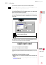
Layer priority and offset
It shows the data of the layer selected by the cursor. For each layer, one must define
its priority and offset (height) on the perpendicular axis.
• The priority defines the order in which the layers will be executed; i.e. the order
in which they will be included in the part-program. Those with priority ·1· will be
executed first and so on.
• The offset (height) on the perpendicular axis permits executing each layer in the
desired Z coordinate (or that of the relevant perpendicular axis).
Work plane
The work plane must be defined before importing the file in the part-program. The
plane is defined by selecting the abscissa axis, the ordinate axis and the
perpendicular axis.
When importing it in the profile editor, the plane will be the one selected at the editor
and only the perpendicular axis can be selected.