RESTRICTED USE ONLY Fargo Electronics, Inc.
DTC500 Series Card Printer/Encoders User Guide (Rev. 5.0)
10
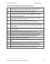
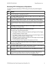
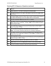
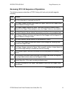
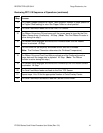
Reviewing DTC 520 Sequence of Operations (continued)
13 Flipper Stepper rotates the Flipper Table a certain number of steps (based on the
Flipper Offset setting) to return the Flipper Table to a level position.
14 The Card Feed Motor feeds the Card to the Print TOF Sensor.
15 The Ribbon Drives turn ON and move until the correct panel is detected by the
Print Ribbon Sensor Array (5 reflective). All Stop. (Note: The Print Ribbon
Encoder is active during this step.)
16 The Headlift Motor engages and moves the Printhead down until the Headlift
Sensor detects a change in state. All Stop.
17 The Fan turns ON (as required) and blows cool air on the Printhead.
(Note: The Printhead Thermistor determines the Printhead Temperature.)
18 Ribbon Drive and Card feed Motors activate and the printhead burns image data
until the image data is depleted. All Stop. (Note: The Ribbon Encoder is active
during this step.)
19 The Headlift Motor engages, moving the printhead up until the Headlift Sensor is
activated. All Stop.
20 The Card Feed Motor feeds the Card back to the Print TOF Sensor.
21 Repeat Steps 14 to 20 for the appropriate Number of Color/Overlay Panels.
22 The Card Feed Motor transports the Card back to the Flipper Table.
23 The Flipper Stepper rotates to invert the Card.
24 The Card Feed Motor activates and moves the Card to the Print TOF Sensor. All
Stop.
25 The Flipper Stepper rotates to return the Flipper Table to a level position.
26 Repeat steps 14 to 20 for the appropriate Number of Color/Overlay Panels.
27 The Card Feed Motor activates to feed the Card out of the Printer.


