


FARGO Electronics Inc.
4-46 HDP700 Series Card Printer
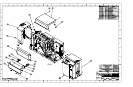
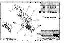
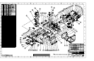
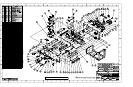
4.9 Replacing the Power Assembly Components
Follow the procedures in this Section to replace the Power Module components.
4.9.1 Power Switch
(120011)
Refer To Drawing 840161
Tools Needed
Torx T-10 Screwdriver, Needle Nose Pliers, Phillips-head Screwdriver
1. Turn off the printer and unplug the power cord from the printer.
2. Remove the screws from the Back Cover of the printer.
3. Tilt the Back Cover outwards from the printer.
4. Remove the two screws (130314) from the Power Supply Cover.
5. Remove the Power Supply Cover.
6. Unplug the Power Supply Cable, the black wires leading into the white plug on the top of the
board.
7. Use the Needle Nose Pliers to unplug the cables that run to the Power Switch and the Line
Filter
NOTE
The cable connectors labeled D840511 goes to the top two connectors; cable D840512 goes to the lower two
connectors for the Line Filter.
8. Depress and hold the tabs on the top and bottom of the Power Switch.
9. Push the Power Switch out of the printer.
4.9.2 Power Cord Receptacle
(130067)
Refer To Drawing 840161
Tools Needed
Torx T-10 Screwdriver, Needle Nose Pliers, Phillips-head Screwdriver
1. Turn off the printer and unplug the power cord from the printer.
2. Remove the screws from the Back Cover of the printer.
3. Tilt the Back Cover outwards from the printer.
4. Remove the two screws (130314) from the Power Supply Cover.
5. Remove the Power Supply Cover.
6. Unplug the Power Supply Cable.
7. Use the Needle Nose Pliers to unplug the cables that run to the Line Filter (130067). Remove
the Ground Screw (D840510).