


FARGO Electronics Inc.
HDP700 Series Card Printer 4-7
4.3 Replacing the Printhead Assembly Components
Follow the procedures in this Section to replace the Printhead Assembly components.
4.3.1 Printhead
(D840854)
Refer To Drawing 840160
Tools Needed
None
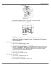
1. Turn off the printer and unplug the power cord from the printer.
2. Open the Front Access Door.
3. Push the Release Lever down to unlock it.
4. Lift the Print Station up and back.
5. Stand at the front of the printer and locate the tab on the back right of the Printhead.
6. Push up on the tab to disengage the Printhead.
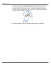
7. Disconnect the two sets of cables on the back of the Printhead. Carefully use a standard
screwdriver if necessary for leverage.
8. Reconnect the two white cables attached to the new Printhead.
9. Install the new Printhead in the printer.
NOTE
Be sure the Printhead can move freely. If it does not, the cable may be tied up too high; adjust it so the
Printhead moves freely.
10. Locate the Printhead Setting Number on the Printhead. The number reads R=XXXX. Be sure
to record this number for later use.
11. Enter this number into the Printhead Resistance option of the Printer Setup menu of
the LCD; if this number is not entered, the printer will generate a Head Resistance Error
when it is turned ON. See Printhead Resistance in Section 7.3.20 for detailed steps.
4.3.2 Fan Assembly
(840134)
Refer To Drawing 840160
Tools Needed
Short-handle Phillips-head Screwdriver, Torx T-10 Screwdriver
1. Turn off the printer and unplug the power cord from the printer.
2. Open the Front Access Door.
3. Push the Release Lever down to unlock it.
4. Lift the Print Station up and back.
5. Remove the four screws (F000034) from the Print Station Cover of the printer.
6. Lower the Print Station back into position.