


FARGO Electronics Inc.
4-38 HDP700 Series Card Printer
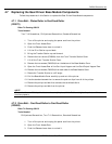
4.8 Replacing the Card Input Hopper Components
Follow the procedures in this Section to replace the Card Input Hopper components.
4.8.1 Flipper Table Sensor Board Assembly
(140407)
Refer To Drawing 840156
Tools Needed
Phillips-head Screwdriver, Torx T-10 Screwdriver
1. Turn off the printer and unplug the power cord from the printer.
2. Open the Front Access Door.
3. Detach the LCD Interface Cable (D840517) from the HD7XXX User Interface Board
Assembly (140403).
4. Remove the five screws from the base of the Card Input Hopper Cover and remove the other
four screws from inside the print station.
5. Lift the Card Input Hopper Cover off of the printer.
6. Remove the three screws that secure the pulley cover and remove.
7. Remove the two screws (F000169) that secure the Flipper Table Home Sensor.
8. Disconnect the Flipper Table Home Sensor Cable.
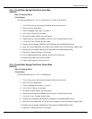
4.8.2 Card Low Sensor Board Assembly
(140407)
Refer To Drawing 840156
Tools Needed
Phillips-head Screwdriver, Torx T-10 Screwdriver
1. Turn off the printer and unplug the power cord from the printer.
2. Open the Front Access Door.
3. Detach the LCD Interface Cable (D840517) from the HD7XXX User Interface Board
Assembly (140403).
4. Remove the five screws from the base of the Card Input Hopper Cover and remove the other
four screws from inside the print station.
5. Lift the Card Input Hopper Cover off of the printer.
6. Remove the three screws that secure the hopper side plate (840217).
7. Remove the three screws from the Pillow Block assembly (0840684) and pull the assembly
towards the back of the printer until free.
8. Remove the hopper side plate from the printer.
9. Remove the two screws (F000169) that secure the Card Low Sensor.
10. Disconnect the Card Low Sensor Cable.