


5. MAINTENANCE, ADJUSTMENTS AND CALIBRATIONS
Page 127 © 2004-2007 DH Instruments, a Fluke Company
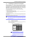
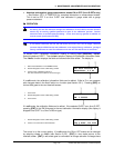
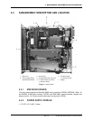
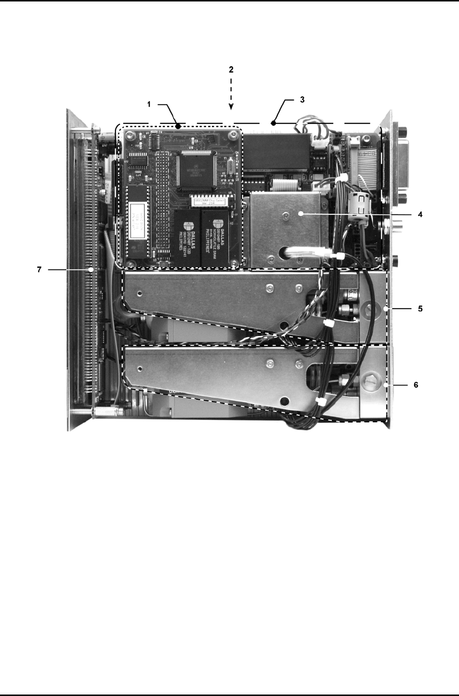
5.5 SUBASSEMBLY DESCRIPTION AND LOCATION
1. Micro Card
2. Power Supply Module
(beneath Driver Board)
3. Driver Board
4. On-Board Barometer (if present)
5. Lo Q-RPT module (if present)
(< A7M style shown)
6. Hi Q-RPT module
(< A7M style shown)
7. Display
Figure 7. Internal View
5.5.1 MINI MICRO BOARD
The micro board supports a Motorola 68302 micro-controller, EPROM, EEPROM, 128k x 16
bit NVRAM, 8 Mbit flash memory; RS-232 and IEEE-488.2 communications; keypad and
display control. An I/O port controls other ports and devices in RPM4.
5.5.2 POWER SUPPLY MODULE
+ 12 V DC (± 2 %) @ 2.1 Amps