


RPM4™ OPERATION AND MAINTENANCE MANUAL
© 2004-2007 DH Instruments, a Fluke Company Page 82
4.2.1.2 IEEE-488
The RPM4 IEEE-488 interface is located on the back of the unit. The physical
and electrical interface conforms to IEEE Std 488.1-1987 Subset E2 and IEEE
Std. 488.2-1992. You should not attempt to communicate with the IEEE-488
interface while using the COM1 interface. The IEEE-488 receive buffer is 250
bytes deep. If you attempt to overflow the buffer, the RPM4 will hold off release
of the NRFD handshake line until it can service and empty the receive buffer.
This keeps the buffer from overflowing. It is recommended that you check for
errors using the “ERR?” query after sending a group of non-query program
messages. When using queries, ensure that you wait for a reply to each query to
ensue proper operation and order of command execution. Replies to queries
remain in the reply queue until the host gets them, so they can “stack up”,
causing replies to appear out of sequence.
4.2.1.3 COM2
The RPM4 COM2 RS232 interface is located on the back of the unit. It can be used
to allow the host computer to communicate with another device through the RPM4.
This allows the user to use one host COM port to communicate with the RPM4 and
an additional RS232 device. Refer to the “#” remote program command for
details. When using the RPM4 as a reference for a PPC3, another RPM4 can be
connected to the first RPM4’s COM2 port, allowing the PPC3 to communicate
with both RPM4s (see Section 3.2.5).
COM2 is a 9-pin female DB-9F connector configured as a DTE device. Data is
transmitted out of the RPM4 using pin 3, and is received on pin 2. This allows a normal
pin-to-pin DB-9M to DB-9F RS232 cable to be used to connect to a DCE device.
Handshaking is not required or supported.
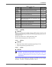
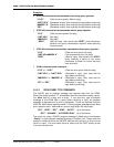
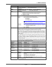
Table 15. COM2 DB-9F Pin Designations
PIN # FUNCTION DESCRIPTION
2 RxD This pin transmits serial data from the RPM4 to a device.
3 TxD This pin accepts serial data from the external device.
4 DTR This pin is Data Terminal Ready (DTR) (held at + 5 V).
5 Grn This pin is the common return for the TxD and RxD signals.
4.3 PROGRAMMING FORMATS
RPM4 supports two program message formats, the “classic”, and the “enhanced” formats. The user
must select which format to use. Selection can be accomplished from the front panel (see Section
3.5.2.3) or remotely using the “L2” or “L3” program message (see Section 4.4.4). The ”MSGFMT”
command can also be used to select the format, but is not recommended for new designs.
The main difference between the “classic” and “enhanced” formats is that when using the IEEE-488 interface,
a query operator “?” must be included in an enhanced command to yield a reply from the RPM4. When
using the COM1 port in classic or enhanced mode or using the IEEE-488 port in classic mode, every
command has a reply which the host must wait for before continuing. In addition, the enhanced message
format supports IEEE Std 488.2 syntax, format and status reporting. The default is the classic format.
In either format, it is recommended that you start out a command sequence with the “*CLS” command,
which clears all of the communication and error queues. The basic commands are similar for both the
classic and enhanced formats, but the usage, syntax, format and status reporting are different.
Many RPM4 classic and enhanced commands are common with PPC2+, PPCK+ and PPC3
Pressure/Controller Calibrators.