


RPM4™ OPERATION AND MAINTENANCE MANUAL
© 2004-2007 DH Instruments, a Fluke Company Page 18
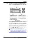
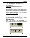
3.1.3 REMOTE [ENT] (ENTER) FOOTSWITCH
The optional remote ENTER function is a switch that duplicates the function of the front panel
[ENT] key. The remote ENTER function is serviced by a connector on the RPM4 rear panel.
An optional footswitch is available to activate remote entry hands free or a different switch
may be used. See Section 7.1 for information on remote ENTER switch wiring.
The remote ENTER feature can be particularly convenient when running AutoTests
(see Section 3.3.10) in which using a footswitch to [ENT] allows hands free operation. It can
also be used, with the FREEZE display function (see Section 3.3.6.6) to capture the
activation point of a pressure switch.
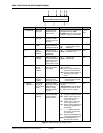
3.1.4 SOUNDS
RPM4 is equipped with a variable frequency tone device to provide audible feedback and
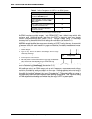
alarms. The beeper is used for the following indications.
Valid key press
Brief beep. Choice between three frequencies or NO
sound is available (see Section 3.5.5.2).
Invalid key press
Descending two tone “blurp”
Leak check completed
Three two second beeps (see Section 3.3.5).
Upper or lower limit exceeded
Intermittent one second beeps (see Section 3.4.4).
Pmax! (overpressure limit)
exceeded
Eight second high frequency beep (see Section 3.4.4.1).
Parallel measurement mode
possible disconnection of the
Hi and Lo Q-RPTs
Rapid beeps for 8 seconds (3.2.4).
AutoTest in/out of tolerance
reading
Ascending triad/descending triad (see Section 3.3.10).
3.2 GENERAL OPERATING PRINCIPLES
3.2.1 PRESSURE READY/NOT READY
There is a Ready/Not Ready indication LED on the RPM4 front panel. This indication is
intended to provide the user with a clear and objective indication of when a stable pressure
has been achieved. Ready is indicated when the current stability (rate of change) of
pressure is less than the stability limit. The user can set the stability limit (see Section 3.4.3).
The ready indication is often used when comparing the RPM4 and a test device to indicate
when a valid reading can be made.
In RPM4s with two Q-RPTs, the Ready/Not Ready indication always applies to the active
Q-RPT, whose pressure measurement is displayed on the top line of the RPM4 display.
When the inactive Q-RPT measurement is displayed on the second line using the RPT
display mode, the Ready/Not Ready indication for the inactive RPT is indicated by the
leading character on the line. <Σ> indicates Ready. <
↑
> or <
↓
> indicate Not Ready,
pressure increasing or pressure decreasing.
The Ready/Not Ready LED indications are:
<Green > Pressure Ready The pressure stability is within the stability limit.
<Red> Pressure Not Ready The pressure stability is NOT within the stability limit.