


RPM4™ OPERATION AND MAINTENANCE MANUAL
© 2004-2007 DH Instruments, a Fluke Company Page 128
5.5.3 DRIVER BOARD
The driver board is controlled by the mini micro board (see Section 5.5.1). It supports:
• 12 V drivers for internal solenoid valve actuation
• Frequency counters (2) for reading Q-RPTs (see Section 5.5.5)
• On-board barometer power and output (see Section 5.5.4)
• Utility sensor (if present) power and output
• Power to the system cooling fan
• Remote [ENT]
• Keypad and display
• Beeper
5.5.4 ON-BOARD BAROMETER
The on-board barometer supports a board mounted, barometric range, micromachined
silicon sensor and an ambient temperature sensor. The barometer readings are used for
dynamic atmospheric pressure compensation when measuring gauge pressure with an
absolute quartz reference pressure transducer (see Section 3.2.2). The temperature sensor
is used for temperature compensation of the barometric sensor.
RPM4s that have only G100K or G200K Q-RPTs (no Axxx or G15K or BGxxx) are NOT
equipped with an on-board barometer.
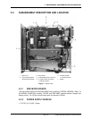
5.5.5 Q-RPT MODULE
The Q-RPT module is an integrated Quartz Reference Pressure Transducer (Q-RPT)
assembly. The module includes a Q-RPT, brackets to hold the transducer, interconnecting
tubing, a manifold with TEST(+),TEST(-) (A70M and lower only) and VENT (ATM on A100M
and higher) ports and SDS (Self Defense System) solenoid valves (A7M and lower, gas
operated, only).
A Q-RPT provides very high precision, low uncertainty pressure measurement. The basic
sensing principle is the measurement of the change in the natural oscillating frequency of a
quartz tuning fork in response to changes in temperature and mechanical stress resulting
from the change in pressure applied to a connecting bellows or bourdon tube. Two independent
quartz elements are used. One quartz element is subjected to pressure related stress. The
other quartz element is used only to monitor temperature. See Section 1.2.2.1 for Q-RPT
specifications.
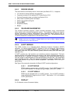
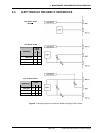
See Figure 8 for pneumatic schematics of different Q-RPT module configurations.
5.5.5.1 HI Q-RPT MODULE
RPM4 is always equipped with a Hi Q-RPT module. The Hi Q-RPT module is in
the Hi Q-RPT position. It is always the higher range in two Q-RPT RPM4s.
5.5.5.2 LO Q-RPT MODULE
RPM4 may be equipped with a Lo Q-RPT module. The Lo Q-RPT provides a
lower measurement range than the Hi Q-RPT. See Section 1.2.2.1 for complete
Q-RPT specifications.
5.5.6 DISPLAY
2 x 20 character vacuum fluorescent display.