108 U41243-J-Z156-1-76
Memory expansion System expansions
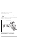
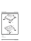
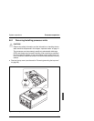
Ê The processor units and FSB terminator modules are secured by fasteners
(one fastener for two processor units).
Remove the appropriate fastener by removing the two screws and tilting the
fastener in the direction of the arrow.
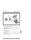
Ê Unlock the FSP terminator or processor unit by simultaneously rotating the
two eject/insert levers (3) outward approximately 90° (see figure 30 on
page 106) to eject the processor unit or terminator from the slot.
Ê Slide the terminator or processor unit out of the slot guides and place it
thermal plate-side up on a non conductive, static-free surface or store it in
an antistatic protective wrapper.
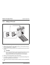
Ê Install a new processor or a terminator (in reverse order) in the empty slot.
Ê Secure the processor unit or terminator with the fastener (two screws).
Ê Replace the top cover (see the section “Removing/mounting the top cover”
on page 88).
8.7 Memory expansion
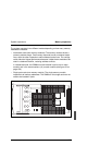
Main memory resides on two carrier boards called memory modules. The
memory modules are located under the control panel on the front of the server
and are connected with the main processor carrier board via a connection
modules.
Each memory modules contains slots for 16 DIMMs. The memory controller
supports PC 100-registered SDRAM DIMMs. Three DIMM sizes are supported:
256 MB, 512 MB and 1 GB. Memory sizes from 256 MB to 16 GB per module
are supported.
One to 32 DIMMs (total number of DIMMs for two memory modules) can be
installed. Each memory module must be populated with an equal number
DIMMs of (see also the section “Installing DIMMs” on page 110) unless only one
DIMM is used.
I If only one memory module is installed, DIMM sizes on that module may
vary, but if both memory modules are installed, the DIMM configuration
on the two modules should be identical to support memory interleaving
for performance gains.


