


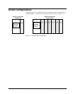
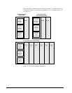
1-6
•
••
•
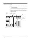
Chapter 1 Equipment Overview GEH-6632 EX2100 User’s Guide
Software Overview
Microprocessor-based controllers (ACLA and DSPX) execute the exciter control
code. The software consists of modules (blocks) combined to create the required
system functionality. Block definitions and configuration parameters are stored in
flash memory, while variables are stored in random-access memory (RAM).
The exciter application software emulates traditional analog controls. It uses an open
architecture system, with a library of existing software blocks configured from the
toolbox. The blocks individually perform specific functions, such as logic gates,
proportional integral (P.I.) regulators, function generators, and signal level detectors.
The control selects one of two modes, either generator voltage regulation (Auto
Regulation), or direct control (voltage or current, depending upon the application).
Generator protection functions are integrated into the control, including over and
under-excitation limiting, power system stabilization, and V/Hz limiting.
The blocks can be interrogated while the exciter is running by using the toolbox. The
dynamically changing I/O values of each block can be observed in operation, which
is valuable during startup or troubleshooting.
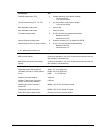
Technical Characteristics
Summary characteristics for the EX2100 are as follows; for further details refer to
Appendix B.
Unit Specific ratings are provided on equipment nameplate and
supercede all information herein.
EX2100 Characteristics Description
Power Converter Module (PCM)
Single bridge rating 1,000 and 2,000 A dc at up to 1,000 V ac
Parallel bridge rating 8,000 A dc at up to 1,500 V ac; with up to 6 bridges
Forcing requirements 150% of design Amperes (EDA) for 30 s at 40 ºC
Power Sources
Power for the PCM – Voltage source
Auxiliary bus
Generator terminals
Compound source
600 or 1,000 V ac versions
Power Input for the PCM - VA 3251 kVA (1,000 V version)
Power for the PCM - Frequency 3-phase 50/60 Hz
Flashing power Battery source 125 V dc or 250 V dc, with up to 200 A for at least 10 s
240 or 480 V ac, 50/60 Hz single-phase auxiliary source
Control power
For two ac sources, or one ac and one dc source:
Nominal 120 V ac ±15%, with 1 DACA, 10 A rms max.
Battery source, 125 V dc, range 80 – 140 V dc, 10.6 A dc max.