


4-8
•
••
•
Chapter 4 Terminal Board I/O and Equipment Connections GEH-6632 EX2100 User’s Guide
Exciter Internal I/O
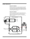
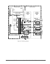
Exciter AC Feedback
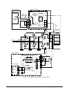
The EACF board measures the exciter ac supply voltage and current. The terminal
board contains transformers for a 3-phase voltage measurement, and terminals for
two flux/air core coils. The cable between EACF and the EBKP control backplane
can be up to 90 m in length. Cable shield terminal screws attached to chassis ground
are located within three inches of the input screws where applicable. There are two
versions of the circuit board, EACFG1 for up to 480 V rms inputs, and EACFG2 for
up to 1000 V rms inputs. Refer to Figure 4-4.
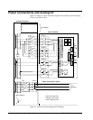
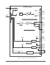
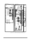
Exciter DC Feedback
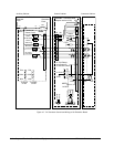
The EDCF board measures field current and field voltage at the SCR bridge, and
interfaces to the EISB board in the controller over a high-speed fiber-optic link. The
fiber optics provides voltage isolation between the two boards, and high noise
immunity. For a circuit block diagram, refer to Figure 4-5. The field voltage
feedback circuit provides seven selector settings to scale down the bridge voltages
appropriate to the application.
DC
Shunt
Shunt
mV
input
+
-
-
+
SCR Bridge
Field
+
-
JP1
JP7
scale 1
scale 7
Stab-on
R1
R 9
Ra
ACOMH
ACOMH
I feedbk
V feedbk
To
EISB
board
Voltage
Isolation
Barrier
30 Vdc
max.
COM
+/-24Vdc
from
External
Source
EDCF DC Feedback Board
1
2
3
4
+24V
-24V
J16
+ 24 V dc
- 24 V dc
+ 15 V dc
- 15 V dc
+ 5 V dc
DC/AC
Inverter
AC/DC Converter
& Power Supplies
Field Voltage
Amplifier
Field Current
Amplifier
Tx2
Tx1
Fiber Optic Link
Figure 4-5. Field Voltage and Current Measurement