


EX2100 User’s Guide GEH-6632 Chapter 2 Functional Description
•
••
•
2-9
Shaft Voltage Suppressor
The Shaft Voltage Suppressor
protects the shaft bearings.
Excitation systems, which produce a dc voltage from ac through a solid state
rectification process, produce ripple and spike voltages at the exciter output. Due to
their rapid rise and decay times, these voltages are capacitively coupled from the
field winding to the rotor body. This creates a voltage on the shaft relative to ground.
Shaft voltage, if not effectively controlled, can be damaging to both journals and
bearings. The shaft voltage suppressor is a filter that conducts the high frequency
components of the induced voltages to ground. (This filter is shipped loose in some
cases, otherwise it is part of the lineup).
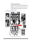
Field Flashing Module
The field flashing module is provided on generator terminal fed excitation systems. It
supplies initial exciter current and builds generator voltage, supplying approximately
10% - 15% of no-load field current from the station batteries during the startup
sequence. If large machines require ac field flashing, the ac power is supplied
through an isolation transformer. Both designs require customer supplied power.
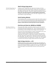
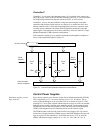
Field Ground Detector (EXAM and EGDM)
The field ground detector
protects the generator shaft.
The generator field winding is electrically isolated from ground. The existence of
one ground usually does not damage the rotor. However, the presence of two or
more grounds in the field winding path causes magnetic and thermal imbalances and
localized heating, which may damage the rotor forging or other metallic parts.
The function of the field ground detector is to detect a ground path from any exciter
component connected to and including the main field windings.
The Exciter Attenuator Module (EXAM) drives the electrical center of the field
winding with a low frequency ac voltage relative to ground. To detect the current
flow, the voltage across a sensing resistor is picked up by EXAM and measured by
the EGDM module. This signal is sent over a fiber-optic link to the controller where
it is monitored and alarmed. The EGDM boards (1 for simplex and 3 for redundant)
are mounted in the control power supply module located in the control cabinet.
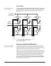
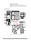
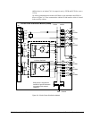
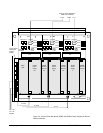
High Voltage Interface – HVI
The HVI contains the ac and dc bus, plus the line filter fuses. It also contains two
terminal boards providing bridge feedback to the control and the EXAM board. The
EACF board accepts incoming PPT ac voltage and air core CT current signals. It has
transformers to isolate the voltages and produce low level signals. The EDCF board
measures the bridge dc current and voltage, and sends it over fiber-optics to the
control.