


2-10
•
••
•
Chapter 2 Functional Description GEH-6632 EX2100 User’s Guide
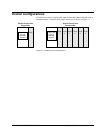
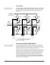
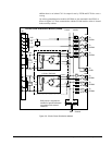
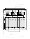
Control Cabinet
The control cabinet contains the keypad control rack, control power distribution
module and supplies, and I/O terminal boards.
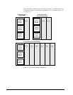
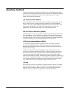
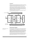
Diagnostic Interface (Keypad)
A second keypad is provided
for redundant controls.
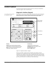
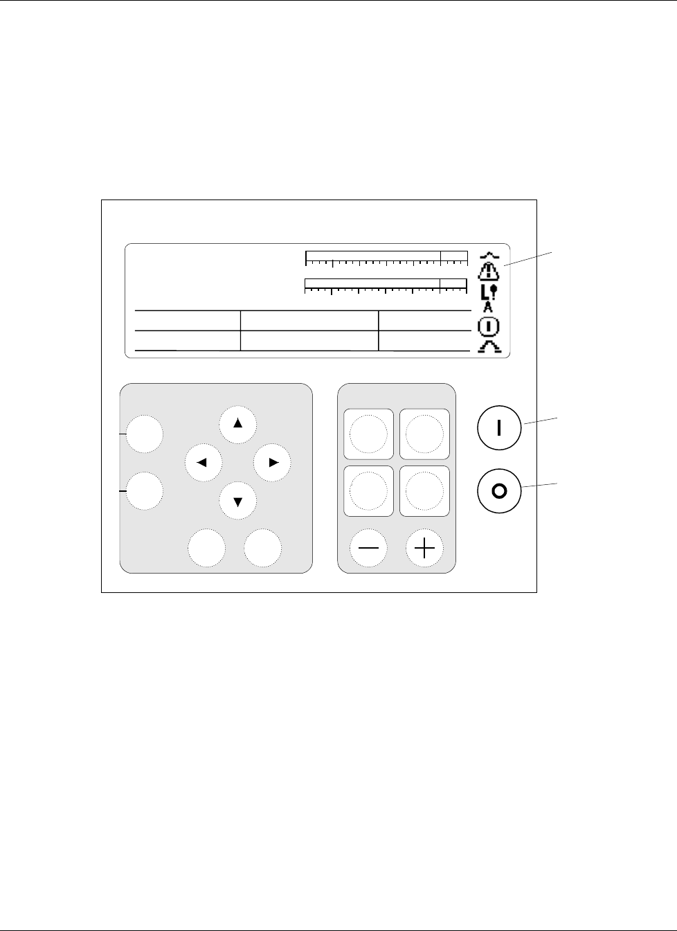
The keypad is a local operator interface that is mounted on the control cabinet door.
Refer to Figure 2-4 for a view of the keypad and a summary of the operator and
maintenance functions available. Chapter 5 describes the keypad in detail.
Display:
Status
screens provide analog and digital
representation of exciter functions and values.
Menu
screens provide text-based access to
parameters, wizards, and faults.
Pushbuttons:
Organized into functional groups:
Navigation
buttons for using the menu
Exciter Control
buttons
Run
and
Stop
buttons
Exciter Health
& State Icons
Run (Green)
Stop (Red)
Reset
Faults
Command
Menu
Voltage Level
Exciter Control
Status
Menu
EnterEscape
Navigation
FVR Feedback
0.0 Volts
FldCurrAmps
0.00 Amps
EX2100 Excitation Control
g
-30%
0% 150%
Auto
Man
On
Off
100%
Vmag
Freq_Hz
Imag
Watts
Balance Meter Vars
0.00
0.000.00
60.00
0.00
0.00
-30%
0% 150%
100%
Figure 2-4. Diagnostic Interface – Keypad
Start/stop commands, regulator transfer commands, and regulator activation
commands can be issued from the keypad. The keypad also includes meter displays
indicating system conditions such as generator MW and MVARs, field current and
voltage, and regulator balance. Diagnostic displays such as the alarm history display
provide system information for maintenance and troubleshooting.