


EX2100 User’s Guide GEH-6632 Chapter 2 Functional Description
•
••
•
2-19
AUTO
REF
PSS
UEL
AVR
Power
System
Stabilizer
Under
Excitation
Limit
Generator
Terminal
Voltage
Watts
AVR
Setpoint
and
Tracking
(VMAG)
Automatic
Voltage
Regulator
FVR
Track
Value
Setpoint
EXASP
Exciter AVR
Setpoint.
Setpoint
V/Hz Limit;
Reactive
Current
Compen-
sation.
Frequency
VMAG
VMAG
Slip
External
Raise/
Lower
MANUAL
REF
FVR
Field
Voltage
Regulator
FCR
Field
Current
Regulator
Min.
Field Voltage Regulator Setpoint
Firing
Commd
to
Bridge
Field Volts from Bridge Output
FCR Setpoint
(User Input)
Field Current from Bridge DC Shunt
External
Raise/
Lower
Watts
VARs
Reactive
Current
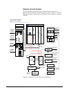
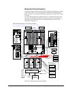
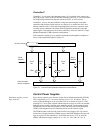
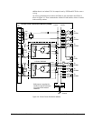
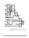
Figure 2-11. Software Block Diagram
The output of the control software is the firing command, which is sent to the bridge
to generate the field current. The individual function blocks are discussed in the
following sections.