


EX2100 User’s Guide GEH-6632 Chapter 4 Terminal Board I/O and Equipment Connections
•
••
•
4-11
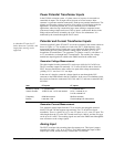
De-Excitation
During shutdown of the generator, the stored energy of the generator field inductance
must be dissipated. In the EX2100 exciter, this is the function of the EDEX
de-excitation module and field discharge resistor or inductor (when supplied).
Standard de-excitation is provided by a freewheeling diode. For higher performance
applications, the de-excitation module consists of a thyristor (53 mm or 77 mm cell
size) mounted in a large heatsink assembly with attached snubber network.
The EDEX board contains Hall effect conduction sensors. The sensors are mounted
in the air gap of a circular steel core attached to the board. They sense the magnetic
field produced by the field discharge current flowing through the thyristor. Two
independent sensor circuits are used. The EDEX fires the SCR when either of two
control inputs is true or when the anode to cathode voltage of the SCR exceeds a
certain value. The two firing control circuits on the board are powered from separate
power supplies and use separate conduction sensors making them mutually
independent.
The actual control logic inputs used are dependent on the application. When the
exciter shuts down, a P24 V firing control signal is sent to both de-excitation module
firing control circuits. Both firing control circuits send gate pulses to fire the de-
excitation SCR. At this point, the main field polarity reversal has occurred making
the SCR anode positive with respect to the cathode. Therefore the SCR conducts and
dissipates the stored energy of the generator field through the field discharge device.
Feedback from either conduction sensor verifies that the discharge circuit has
operated successfully. If both independent firing control circuits fail to fire, the SCR
is fired by the anode firing circuit when the anode to cathode voltage has exceeded
the selected level.
For large exciters, it is possible to connect multiple de-excitation modules together
with one EDEX board configured to be the Master and the other boards configured
to be Slaves. In this case, a firing control signal sent to the Master is relayed to the
Slave modules, firing all modules simultaneously.
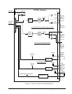
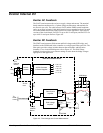
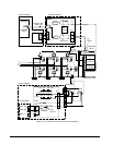
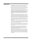
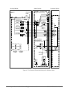
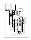
EXTB controls the main breaker or contactor in the field circuit. When this opens,
the auxiliary contacts cause an immediate de-excitation commanded by EDEX. De-
excitation controlled by EXTB in both the contactor and breaker mode is shown in
Figures 4-7, and 4-8.
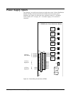
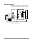
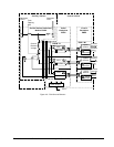
Location of the 41A dc contactor in the field circuit is shown in Figure 4-6.
Contactor 41B is optional. Both contactors are located in the Power Conversion
Cabinet, and are driven from the 41 Close pilot on the EXTB board. Several
auxiliary contacts are used to provide status feedback to the control, and firing
commands to the de-excitation board, EDEX.
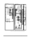
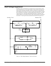
An alternative to an 41A and 41B contactor is to use a breaker in the excitation ac
supply or dc field circuit. Normally, the breaker would be a dc field breaker that
ccould break the output while inserting a discharge resistor with the normally open
contact. But, an ac break with the SCR based de-excitation module could also be
applied. The breaker has two coils, 41 Close and 41 Trip, and auxiliary contacts for
de-excitation. Figure 4-8 shows how the breaker interfaces with the EXTB control
board and EDEX.