


4-4
•
••
•
Chapter 4 Terminal Board I/O and Equipment Connections GEH-6632 EX2100 User’s Guide
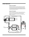
Customer Contact I/O
Customer contact inputs and relay contact outputs are wired to the ECTB board.
In addition to six general purpose contact inputs, there are two dedicated contact
inputs, wetted by 70 V dc from the exciter, as follows:
• 86G contact input used as a lockout during normal operation
• 52G contact input gives the online status of the generator
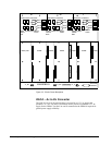
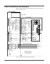
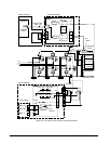
ECTB provides four general purpose Form C contact outputs controlled by EMIO.
These are used for 94EX and 30EX and other outputs. For each relay, the coil current
and the status of a relay auxiliary contact is monitored. These feedbacks are cabled to
EMIO in the controller. Refer to Figure 4-2 and Table 4-1.
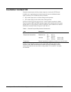
Table 4-1. General Purpose Relay Contact Characteristics:
Item Description
Customer Power 125 V dc nominal (24 V dc min)
Relay break characteristic
Resistive load 2 A 28 V dc
0.5 A 125 V dc
Inductive 1 A 28 V dc 0.007 s (L/R)
0.1 A 125 V dc 0.007 s (L/R)
Suppression External suppression supplied by customer on induction loads
ECTBG1 is the redundant control version of the ECTB. This fans inputs to three
connectors J405, J408, and J418 that are cabled to the three controllers. For relay
control, the board does two-out-of three voting, and the 70 V dc and 24 V dc inputs
are redundant.