


4-6
•
••
•
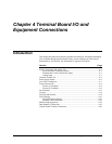
Chapter 4 Terminal Board I/O and Equipment Connections GEH-6632 EX2100 User’s Guide
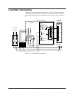
Power Supply Inputs
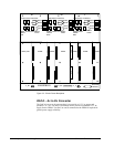
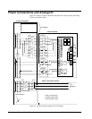
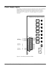
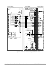
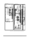
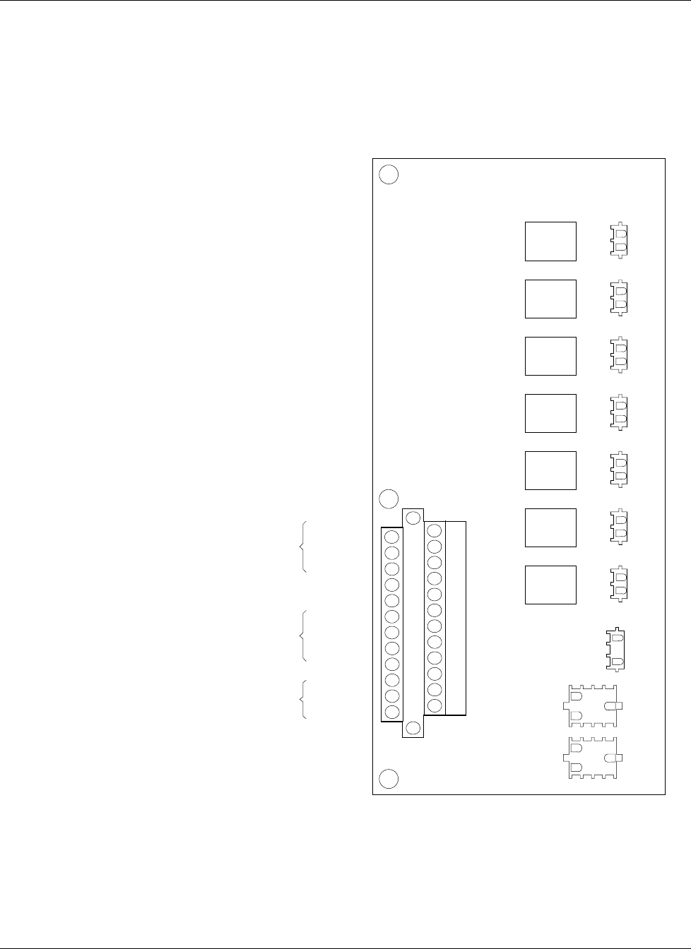
The customer’s ac and dc power inputs are wired to the exciter’s Power Distribution
Module (EPDM), which is located on the left hand side of the exciter power
backplane rack. Figure 4-3 shows the screw terminals for the 125 V dc battery
source, and the 115 V ac suply, AC1. A second ac supply, AC2, can also be
connected.
J9
1
3
1
2
1
2
1
2
1
2
1
2
1
2
1
2
1
10
3
12
JDACA2
JDACA1
1
10
3
12
J8A
J8B
J8C
J1M1
J1M2
J1C
SW3
SW1
SW2
SW4
SW5
SW6
SW7
SPARE
P125Vdc
2
4
6
8
10
12
14
16
18
20
22
24
x
x
x
x
x
x
x
x
x
x
x
x
x
1
3
5
7
9
11
13
15
17
19
21
23
x
x
x
x
x
x
x
x
x
x
x
x
x
TB1
P125Vdc
P125Vdc
N125Vdc
N125Vdc
N125Vdc
AC1H
AC1H
AC1N
AC1N
AC2H
AC2H
AC2N
AC2N
125 V dc
from battery
115 V ac
supply #1
115 V ac
supply #2
EPDM Exciter Power Distribution Module
Figure 4-3. Power Wiring Connections to EPDM.