


EX2100 User’s Guide GEH-6632 Chapter 2 Functional Description
•
••
•
2-13
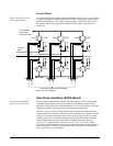
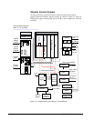
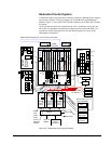
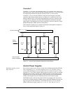
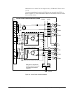
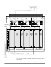
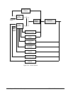
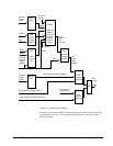
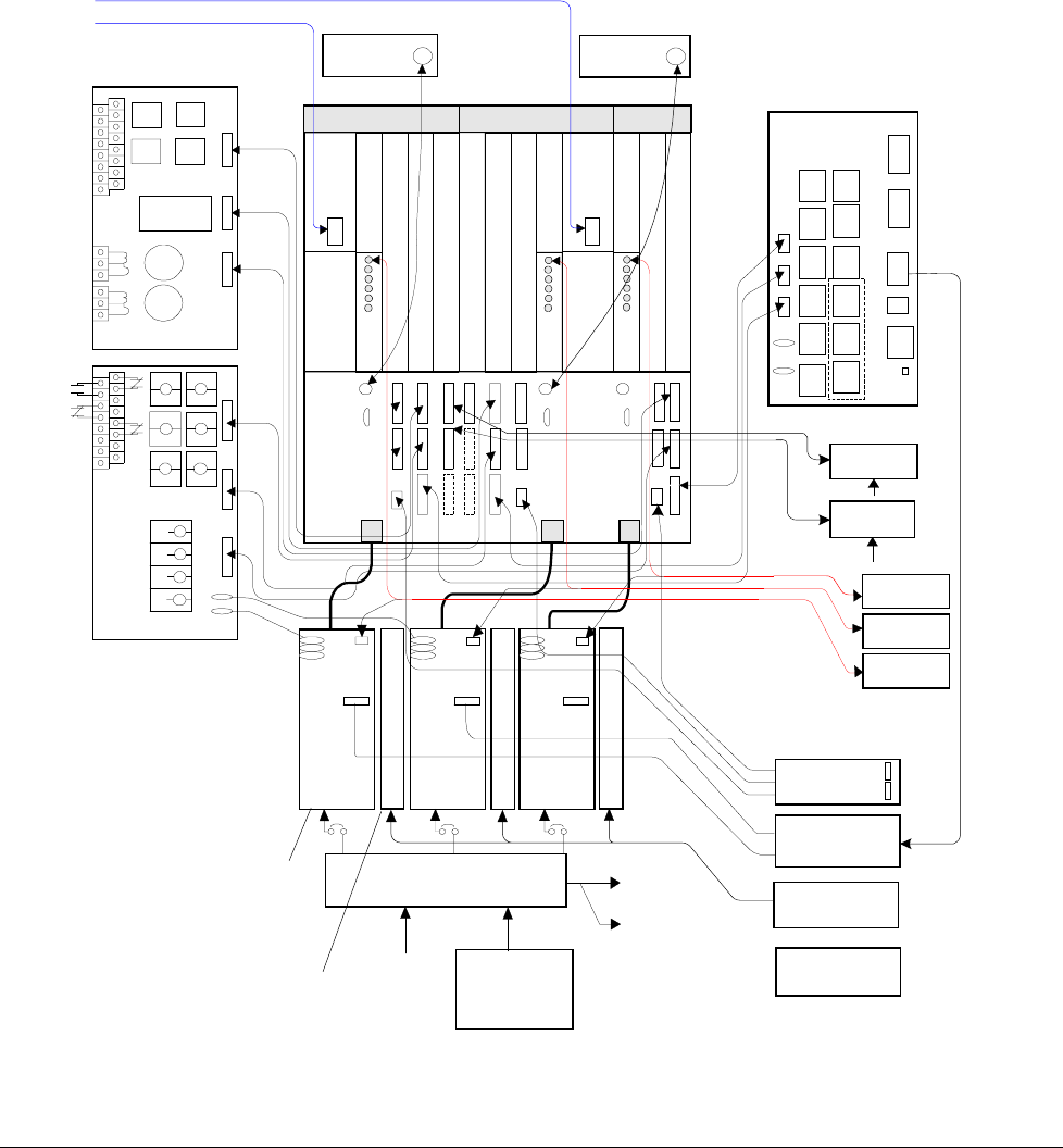
Redundant Control System
A redundant control system has three controllers and three redundant power supplies,
one for each controller. The power supply rack also holds three ground detector
modules. Figure 2-6 shows three EDCF boards, and there can be three EPCT boards,
if required.
Up to two Ethernet cables are connected to the ACLA controllers (one to M1 and
one to M2) for redundant communication with the turbine control and HMIs. Two
keypads are shown connected to M1 and M2. Both keypads have access to the
information in controller C.
PT
CT
TRIP
TRIPTRIP
TRIP
86
8686
86
PT
PT
PT
CT
To Flashing
panel
41 Device
ACLA
DSPX
EPCT
EMIO Master I/0
ESEL
Fan-out
circuits
2nd
2nd2nd
2nd
TRIP
TRIPTRIP
TRIP
ECTB
Bridge 1
ACLA
DSPX
DSPX
EMIO Master I/O
EMIO Master I/0
Bridge 2
Bridge 3
Bridge 4
Bridge 5
Bridge 6
70V
De-
excitation
-125Vdc
Crowbar
Gate Pulse Amplifiers
EISB
ESEL
EISB
EISB
EDCF
EDCF
EDCF
EGPA
125Vdc
EGPA
125Vdc
Power
Supply
EPDM
Coil Power
125 V dc
Battery
125 Vdc
P24V
PN24V
70V
EDEX
De-excitation
EACF
PPT and air core CT
(AC) Feedbacks
Field
Ground
Detector
EGDM
EXTB
53A
pilot
41
trip
41
trip
41
trip
53B
pilot
53B
pilot
53B
pilot
53A
pilot
53A
pilot
41
close
41
close
41
close
Option: Field Breaker
70V
70V
De-ex
pilot
Tool
Ethernet Data Highway to Turbine Control and HMI
EBKP
Backplane
Keypad
Keypad
M2M1
C
Power
Supply
70V
P24V
PN24V
Power
Supply
70V
P24V
PN24V
E
G
D
M
E
G
D
M
E
G
D
M
Fiber-optic Field
V & I feedback
EPSM
EPSM
EPSM
EPBP
back
plane
Option:
DACA
Rectified ac
Optional:
Crowbar
EXAM
Attenuator
GPA power
Figure 2-6. Redundant Control System Cabling