


EX2100 User’s Guide GEH-6632 Chapter 4 Terminal Board I/O and Equipment Connections
•
••
•
4-5
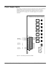
Four General Purpose Relay Outputs as Above
Customer
Power to
Contacts
125 V dc
Two Trip Relay Outputs as Above
P24M1
Customer
Power to
Contacts
125 V dc
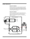
Coil
K#M1
Relay
Driver
M1
M1
J405
Auxiliary
Contact
Input
Six Circuits as Above
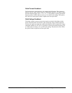
86G
Contact
52G
Contact
P70Vdc
Current Limit
Circuit
Red LED
P70Vdc
Current Limit
Circuit
Red LED
From M1
(EMIO)
P70Vdc
P70 V dc
Coil
K#GP
Relay
Driver
P24D
From M1
J13M1
NO
COM
NC
P24M1
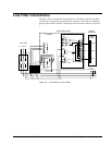
ECTBG2 (Simplex)
TB1
TB2
Current Limit
To Optocoupler on M1 (EMIO)
P24D
18
19
20
1
5
33
34
45
46
47
48
(Open
for Trip)
(Closed
online)
Term. 1&5
Ex. trip to
Customer
86
Ex. Fault
to Mark VI
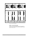
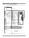
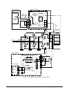
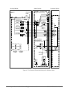
Figure 4-2. Customer I/O wired to ECTBG2 Simplex Board