


2-2
•
••
•
Chapter 2 Functional Description GEH-6632 EX2100 User’s Guide
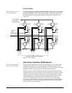
Exciter Hardware
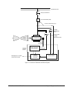
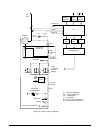
The EX2100 exciter consists of the following basic components.
• Power Conversion Module (PCM) and cooling fans
• Power potential transformer (PPT) (mounted separate from exciter)
• Line-to-line filters
• Shaft voltage suppressor
• De-excitation module
• Diagnostic Interface (keypad)
• Controllers and I/O boards
• Control power supplies
Optional components that can be added to the exciter are:
• Warm backup bridge configuration
• Multibridge configuration for high current requirements
• Compound power source (separate from exciter)
• Auxiliary power source (bus-fed)
• Crowbar module (for hydro and other special applications)
• Dc Disconnect
• Field ground detector
• Redundant ac source for power supply
• Ac disconnect
• Field flashing module
• Redundant controllers providing a Triple Modular Redundant (TMR) system
• GE Control System Toolbox (toolbox) for configuration
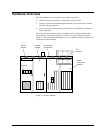
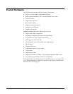
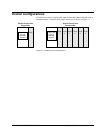
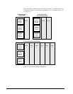
The control hardware is basically the same for the different types of excitation. The
power conversion hardware is defined by application requirements, which therefore
determines the exciter bridge size.