


4-20
•
••
•
Chapter 4 Terminal Board I/O and Equipment Connections GEH-6632 EX2100 User’s Guide
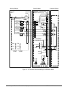
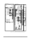
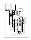
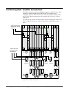
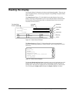
Control System Toolbox Connection
The toolbox connector on the exciter backplane supports an RS-232C cable, which
connects an external computer to the DSPX board. This connection is for
maintenance purposes. There are three 9-pin connectors located at J303B, J310B,
and J313B to support communication with controllers M1, M2, and C. (Refer to
Figure 4-13).
The UDH can also provide a toolbox interface using the Ethernet port on the ACLA.
This is a 10BaseT port and uses an RJ-45 connector for unshielded twisted pair
cable.
J304 J305 J306 J307 J308 J309
J405J404 J406 J407 J408 J409
J509J508J507J506J505J504
M1
Power
M2
Power
C
Powr
Tool M1 Tool M2
Key Pad
M1
Key Pad
M2
E
G
P
A
1
E
G
P
A
2
E
G
P
A
3
E
G
P
A
4
E
A
C
F
E
G
P
A
5
E
G
P
A
6
E
A
C
F
DSPX
EMIO ESEL ESEL EMIO
DSPX ACLAACLA
EISB EISB
EMIOEISB
J315J314
J414 J415
J515J514
E
A
C
F
Tool C
Key Pad
C
DSPX
Test Rings M1 Test Rings M2 Test Rings C
J602 J610 J612
IS200EBKP
2
1
2
1
Toolbox RS-232C
Computer Cable
Connections
E
X
T
B
E
C
T
B
E
P
C
T
E
P
C
T
E
P
C
T
E
C
T
B
E
C
T
B
E
X
T
B
E
X
T
B
UDH Ethernet Data
Highway to Toolbox
and HMI
Figure 4-13. Toolbox Connections