


EX2100 User’s Guide GEH-6632 Chapter 4 Terminal Board I/O and Equipment Connections
•
••
•
4-17
13
42
EXTB
3
12
6
9
5
2
10
4
J7
J5M1
M1 53B
M2 53B
C 53B
M1 53A
M2 53A
C 53A
P70Vdc
P70VDC
M1-EMIO
(J5)
M2-EMIO
(J5)
C-EMIO
(J5)
P70Vdc
P70VM1
P70VM2
6
53B
53A
9
5
2
10
4
J7
3
12
53A
Aux
1
2
1
2
SUP
3
4
SUP
B
B
A
A
Current
Limit
Circuit
Current
Limit
Circuit
Auxiliary Panel
Generator
Field -
x
1 2
PTB-1
53B
53A
+
-
Station Battery
125 Vdc
x
From
Shunt1 +
w v
53B
Y
Y
Flashing
J1
53B
Aux
7
8
4
5
6
1
2
3
1
2
3
EXAM
J1
FBK1
FU1
FU2
J5M2
J5C
TB1
Shaft Voltage
Suppresser
132
K53A relay
contacts
K53B relay
contacts
M1
M2
CM2
C
M1
M1
M2
C
M2
C
M1
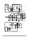
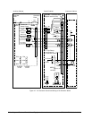
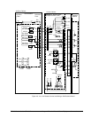
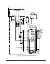
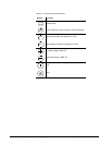
Figure 4-10. Field Flashing Control from EMIO and EXTB