


EX2100 User’s Guide GEH-6632 Chapter 2 Functional Description
•
••
•
2-17
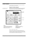
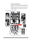
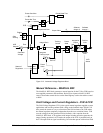
Exciter Software
The exciter software is configured and loaded from the toolbox, and resides in the
controllers. The software is represented on the toolbox screen by control blocks
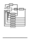
linked together to show the signal flow. Figure 2-10 is a simplified overview of the
exciter control system displaying the main control functions. Both the generator field
and stator currents and voltages are measured and input to the control system. In
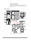
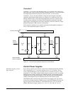
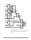
normal operation the ac regulator is selected. Figure 2-11 is the simplified software
block diagram displaying the main control blocks.
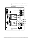
The generator voltages and currents from the PTs and CTs are wired to the EPCT
board, which acts as a signal conditioner to isolate and scale the signals. The
conditioned signals are then fed to the controller. Software conversion algorithms
use these signals to calculate system variables for use by the regulator, limiter, and
protection functions. The outputs from these software calculations include the
following:
• Generator voltage magnitude and generator frequency derived from the PTs
• The magnitude of generator current derived from the CTs
• Generator power, P
• Generator reactive volt amperes (VARs), Q
• Change in rotor speed calculated from the integral of accelerating power that is
normally used as the input to the optional Power System Stabilizer (PSS)
• Generator active and reactive current
• Magnitude of generator flux (VHz)
• Line voltage derived from the PTs
• Line frequency derived from line PTs
• Phase angle correlation between the generator and line, derived from generator
and line PTs