


2-22
•
••
•
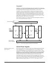
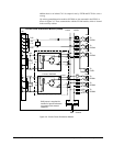
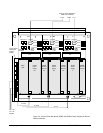
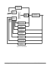
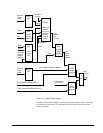
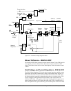
Chapter 2 Functional Description GEH-6632 EX2100 User’s Guide
voltage regulator loop such as compound exciters and some high ceiling exciters, the
FVR uses a setpoint from either the AVR or the MANUAL REF block, and is
always operational whether in manual or automatic operation.
The Field Current Regulator (FCR) is a special application of the manual regulator
and uses the generator field current as the feedback input. The current setpoint is
generally switched between a high level and lower level to provide transient forcing
capability as well as steady state operation within the capability of the generator.
Generally the setpoint is larger than expected field currents and the integral preset is
operational. The FCR output is held at positive ceiling until enable becomes true
which allows the output to follow the P+I regulator. The bridge firing command is
the smaller of the FVR and FCR outputs. While it does regulate constant field
current over varying field temperature, FCR is not the standard manual regulator.
Under Excitation Limiter – UEL
The UEL block is an auxiliary control to limit the automatic voltage regulator
demand for underexcited reactive current (or reactive power). UEL prevents
reduction of the generator excitation to a level where the small-signal (steady state)
stability limit, or the stator core end-region heating limit is exceeded. Performance is
specified by identifying the region of limiter action on the generator capability curve.
There is both a setpoint section and regulator section of the UEL. The two key inputs
are generator terminal voltage and real power.
Power System Stabilizer – PSS
The PSS block provides an additional input to the automatic regulator to improve
power system dynamic performance. A number of different quantities may be used
as inputs to the PSS, such as shaft speed, frequency, synchronous machine electrical
power, accelerating power, or some combination of the above. The PSS used with
the exciter is multi-input using a combination of synchronous machine electrical
power and internal frequency (which approximates rotor speed) to arrive at a signal
proportional to rotor speed. This comes from the integral of accelerating power, but
with shaft torsional signals greatly attenuated. The input signal is derived entirely
from generator terminal quantities without the need for shaft speed transducers. No
additional external hardware is required.