


EX2100 User’s Guide GEH-6632 Chapter 2 Functional Description
•
••
•
2-23
Operator Interface
The HMI contains exciter and
turbine graphic displays.
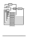
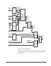
Operator and engineering work stations such as the HMI (Human Machine Interface)
and the toolbox communicate with the exciter. This allows operator monitoring and
control of the exciter, and engineering access to system diagnostics and control
block configuration
Turbine Control HMI
An HMI can be mounted in a
control console or on a
tabletop.
On turbine generator sets that include Mark VI turbine controls, the exciter shares
the HMI. The HMI is Windows NT
®
based with CIMPLICITY operator display
software and communication drivers for the data highways. From the HMI, the
operator can initiate commands and view real-time data and alarms on the
CIMPLICITY graphic displays. An HMI can be configured as a server or viewer,
and can contain tools and utility programs.
Redundant cable operation is
optional and, if supplied,
operation continues even if
one cable is faulted.
The Unit Data Highway (UDH) connects the exciter with the HMI or HMI/Data
Server. The network is 10BaseT Ethernet, and uses separately powered network
switches. For longer runs, fiber-optic cables can be used.
Control System Toolbox (toolbox)
The toolbox is used to configure and maintain the exciter. Control blocks and
diagrams can be modified by configuration and loaded into the control. With the
exciter online, real-time data is available on the toolbox screen, including control
system diagnostics for troubleshooting. The toolbox software runs on an HMI server
or a separate PC on the UDH. Direct connection to the controller DSPX board is also
possible through the Tool port on the control rack backplane.