


3-8
•
••
•
Chapter 3 Printed Wiring Boards Overview GEH-6632 EX2100 User’s Guide
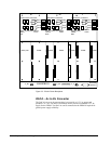
In a redundant system, the set of three EGDM boards are configured as a Controller
(C), Master 1 (M1) and Master 2 (M2). The configuration for each EGDM is
controlled by a set of program pins on the P2 connector. The C controller receives
information from the active DSPX on which EGDM master should provide the drive
signal to the sense resistor in the Attenuator Module. The active master receives an
Oscillator Signal over the fiber optic link that it converts to a ±50 V signal. This is
applied to one end of the sense resistor in the Attenuator Module.
The signal conditioner receives an attenuated (10:1) differential signal from the
Sense Resistor. This is a simple unity gain differential amplifier with a high
common-mode rejection ratio followed by an A-to-D converter (Voltage Controlled
Oscillator VCO). This feeds a fiber-optic transmitter that is cabled to EISB. The
signal conditioner circuitry is powered by an isolated power supply to maintain
personnel and equipment safety due to the high common-mode voltage at the Sense
Resistor. For more information refer to Chapter 4 and GEI-100467.
EXAM Module
The EXAM mounts in the auxiliary cabinet and contains a sense resistor connected
to a resistor network across the field. EXAM applies the low frequency ±50 V
square-wave signal, supplied from the EGDM, to one end of the sense resistor. The
resulting current generates a voltage across the resistor, that is sent back to the
EGDM.
In a redundant system, the test signal can come from either, M1 or M2. EXAM has a
relay that switches between the two under the control of controller C. A single cable
carries the control and sense signals between the EGDM and EXAM modules. For
more information refer to Chapter 4 and GEI-100467.