


2-6
•
••
•
Chapter 2 Functional Description GEH-6632 EX2100 User’s Guide
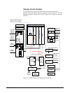
Current Shunt
EDCF provides dc current
and voltage feedback
A dc shunt provides the bridge output current feedback signal. The mV output signal
is input to a differential amplifier on the EDCF board. The amplifier output voltage
controls the frequency of an oscillator, which generates a fiber-optic signal sent to
the control module. The bridge output voltage feedback signal is generated in a
similar way.
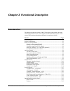
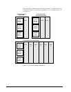
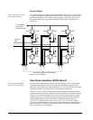
SCR1
SCR4
SCR2
SCR5
SCR3
SCR6
J1
J2 J5
J3
J6J4
FU1A
FU1B FU2A FU2B
FU3A
FU3B
FU4A FU4B FU5A
FU5B
FU6A
FU6B
Snubber 6
To dc Breaker,
Shunt, and
Generator Field +
Gen. Field -
Snubber 3
Snubber 2
Snubber 5
Snubber 4
Snubber 1
Ac power
Input
Gate Driver Inputs from EGPA Board
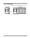
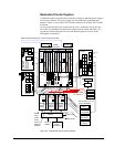
Figure 2-3. Power Bridge
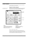
Gate Pulse Amplifiers (EGPA Board)
The gate pulse amplifiers
directly control the SCRs.
The EGPA board interfaces the control to the Power Bridge. EGPA takes the gate
commands from the ESEL board in the controller, and generates the gate firing
pulses for six SCRs (Silicon Controlled Rectifiers). It is also the interface for current
conduction feedback, and bridge airflow and temperature monitoring.
On a new exciter, an RTD is used to monitor the temperature and generate alarms
instead of the Klixon switches. Additional switches actuated by fan rotation monitor
cooling air flow across the bridge. On an exciter controls only retrofit, the exciter
may have provisions for accepting feedback from two thermal switches mounted
on the SCR heatsink assemblies. One thermal switch opens at the alarm level
(170 °F (76 °C)) and the other at the trip level (190 °F (87 °C)). These switches
are wired to the EGPA board and may require retrofitting into the existing bridge. If
either switch opens, a bridge overtemperature alarm is generated. If both switches
open, a fault and a trip are generated.