


EX2100 User’s Guide GEH-6632 Chapter 2 Functional Description
•
••
•
2-5
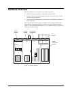
Power Conversion Cabinet
The Power Conversion cabinet contains the Power Conversion Module (PCM), the
Exciter Gate Pulse Amplifier (EGPA) board, ac circuit breaker, and the dc circuit
contactor. Three-phase power for the PCM comes from a PPT external to the exciter.
The ac supply comes into the cabinet through the ac circuit breaker (if supplied), and
is filtered by 3-phase line filters in the auxiliary cabinet.
Manual Ac Disconnect (Optional)
The manual ac disconnect switch serves as a disconnect device between the
secondary of the power potential transformer and the static exciter. It is a molded
case, 3-phase, non-automatic, panel-mounted switch, which is manually operated for
isolating the ac input supply. It is a no-load disconnect device.
Power Conversion Module (PCM)
The exciter PCM includes the bridge rectifiers, dc leg fuses, thyristor protection
circuitry (for example, snubbers, filters, and fuses) and leg reactor assemblies. The
components vary for different bridge ratings based on the power output required.
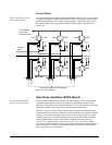
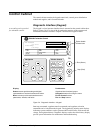
Bridge Rectifier
Each bridge rectifier is a 3-phase full-wave thyristor bridge The bridge has six SCRs
(thyristors) controlled by the Exciter Gate Pulse Amplifier board (EGPA) as shown
in Figure 2-3. Heat is dissipated through large aluminum cooling fins and forced air
flow from overhead fans.
Leg Reactors and Cell Snubbers
The commutating reactors are located in the ac legs feeding the SCRs, and the
snubbers are an RC circuit from the anode to the cathode of each SCR. The cell
snubbers, line-to-line snubbers and line reactors together perform the following
functions to prevent misoperation of the SCRs.
• Limit the rate of change of current through the SCRs and provide a current dump
to aid in starting conduction.
• Limit the rate of change in voltage across the cell and, during cell commutation,
limit the reverse voltage that occurs across the cell.
The SCR snubbers include PRV resistors to limit the peak reverse voltage. These
resistors can be removed if required.
Three-phase input power is fed to the bridge from the secondary of the PPT, either
directly or through an ac breaker or disconnect, and a line-to-line filter. With
inverting bridge designs, the bridge is capable of negative forcing voltage, which
provides fast response for load rejection and de-excitation. The dc current output of
the bridge is fed through a shunt, and on some designs a contactor (41A or both 41A
and 41B) to the generator field. The bridge design utilizes dc leg fuses to protect the
SCRs from overcurrrent.