


EX2100 User’s Guide GEH-6632 Chapter 4 Terminal Board I/O and Equipment Connections
•
••
•
4-1
Chapter 4 Terminal Board I/O and
Equipment Connections
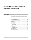
Introduction
This chapter describes the customer's equipment connections, and inputs and outputs
(I/O) available through terminal board wiring. System cabling to provide desired
functionality is also defined. The information is organized as follows:
Section Page
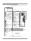
Power Connections and Analog I/O......................................................................... 4-2
Power Potential Transformer Inputs................................................................. 4-3
Potential and Current Transformer Inputs ........................................................ 4-3
Analog Input..................................................................................................... 4-3
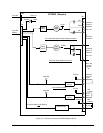
Customer Contact I/O .............................................................................................. 4-4
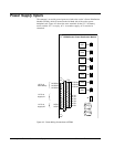
Power Supply Inputs................................................................................................ 4-6
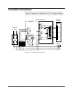
Line Filter Connections............................................................................................ 4-7
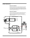
Exciter Internal I/O .................................................................................................. 4-8
Exciter AC Feedback........................................................................................ 4-8
Exciter DC Feedback........................................................................................ 4-8
De-Excitation......................................................................................................... 4-11
Crowbar ................................................................................................................. 4-14
Field Ground Detector ........................................................................................... 4-14
Field Flashing ........................................................................................................ 4-16
Dc Field Flashing Settings.............................................................................. 4-16
Flashing Control Sequence............................................................................. 4-16
Shaft Voltage Suppressor....................................................................................... 4-18
Data Highway Connections ................................................................................... 4-19
Control System Toolbox Connection..................................................................... 4-20