


EX2100 User’s Guide GEH-6632 Chapter 3 Printed Wiring Boards Overview
•
••
•
3-5
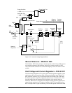
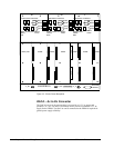
I/O Terminal Boards
The exciter terminal boards are as follows:
• IS200EPCT Exciter PT/CT board (EPCT)
• IS200ECTB Exciter Contact Terminal Board (ECTB)
• IS200EXTB Exciter Terminal Board (EXTB)
• IS200EDCF Exciter Dc Feedback board (EDCF)
• IS200EACF Exciter Ac Feedback board (EACF)
EPCT Board
EPCT receives and conditions
generator PT and CT
feedbacks.
The EPCT contains isolation transformers for critical generator voltage and current
measurements. Two three-phase generator PT voltage inputs are input to EPCT. Two
generator CT current inputs, with current levels of 1 A or 5 A, are input. In addition,
one analog input, which can be either 0-10 V or 4-20 mA, is brought into EPCT. All
the signals are interfaced to the EMIO board. For more information refer to Chapter
4 and GEI-100459.
ECTB Board
The ECTB board supports excitation contact outputs and contact inputs. There are
two versions; the ECTBG1 board which is only used in the redundant mode, and the
ECTBG2 board which is only used in the simplex mode. Each board contains two
trip contact outputs driving a customer lockout, and four general purpose Form-C
relay contact outputs, controlled by the EMIO board. Six auxiliary contact inputs are
powered (wetted) with 70 V dc by ECTB. Also, the 52G and 86 G contact inputs are
powered and monitored by ECTB. In the redundant case, power comes from the M1
and M2 power supplies. For more information refer to Chapter 4 and GEI-100457.
EXTB Board
EXTB handles field flashing
and protection functions.
The EXTB board supports pilot relay contact outputs, contact inputs, and signal
conditioning circuits. EXTB cables to the EMIO board through the EBKP
backplane.
Pilot relays for the breaker/contactor close 41, and flashing contactors 53A, and 53B
are located on the board, plus pilot relays for the trip relay 41T and the de-excitation
relay KDEP. Crowbar status signals and de-excitation status signals from the EDEX
board are conditioned on EXTB and sent to EMIO. Three contact inputs from 41,
53A, and 53B are powered (wetted) by 70 V dc on EXTB. Power for the contacts is
from the M1 and M2 power supplies (redundantly), and the resulting status signals
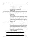
are sent to EMIO in the control rack. Different groups of EXTB are available for
controlling either a field breaker or a contactor in the field circuit. These groups are
defined in Table 3-1. For more information refer to GEI-100458.
Table 3-1. EXTB Board Groups
Type of Redundancy Board Control Mode
Trip Rela
y
41T used
Close Rela
y
41 used
Redundant control EXTB G1 Contactor Mode No Yes
Redundant control EXTB G3 Breaker Mode Yes Yes
Simplex control EXTB G2 Contactor Mode No Yes
Simplex control EXTB G4 Breaker Mode Yes Yes