


Removing and installing components
Component locations
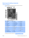
The following illustration and table identify workstation system board components.
Figure 5-1 System board component locations
Table 5-2 System board components ID
Item Component Item Component Item Component
1 CPU fan 12 Clear CMOS button 23 PCI 32/33
2 Rear chassis fan 13 Front power button/LED 24 PCIe2 x16
3 CPU power 14 Crisis recovery jumper 25 PCIe x8(4)
4 Solenoid hood lock 15 Front chassis fan 26 PCIe2 x16
5 CPU socket 16 HDD LED 27 PCIe2 x8(4)
6 Memory sockets 17 Internal USB 1/DASH 28 Audio
7 Main power 18 SATA ports 29 Network/USB
8 Battery 19 Internal USB 2 30 USB
9 Floppy disk drive 20 Front USB 31 Keyboard/mouse
10 Password jumper 21 Speaker 32 Serial
11 Chassis intrusion switch 22 Front audio
For related system architecture information, see System board architecture on page 1.
ENWW Removing and installing components 65